
Electronic device with connecting assemblies

a technology of connecting assembly and electronic device, which is applied in the direction of computing, electrical apparatus casing/cabinet/drawer, instruments, etc., can solve the problems of difficult coupling of female usb connector with male connector of external electronic device, and difficulty in accurately positioning the connecting port in an electronic devi

Inactive Publication Date: 2013-07-18
FU TAI HUA IND SHENZHEN +1
View PDF7 Cites 0 Cited by
  • Summary
  • Abstract
  • Description
  • Claims
  • Application Information

AI Technical Summary

Benefits of technology

The patent text describes the difficulties of accurately positioning and connecting Nicks on electronic devices to external devices through small ports. Additionally, the text explains how the space between the two connectors makes it easy for the USB connector to become loose. The technical effect of this patent is to provide a solution for more reliably and securely connecting electronic devices to external devices through small ports.

Problems solved by technology

It may be difficult to accurately position the connecting port in an electronic device because of the small size and reduced height of the connecting port.
A male connector of an external electronic device may be difficult to be coupled with the female USB connector.

Method used


Image

  • Electronic device with connecting assemblies
  • Electronic device with connecting assemblies
  • Electronic device with connecting assemblies

Examples


Embodiment Construction

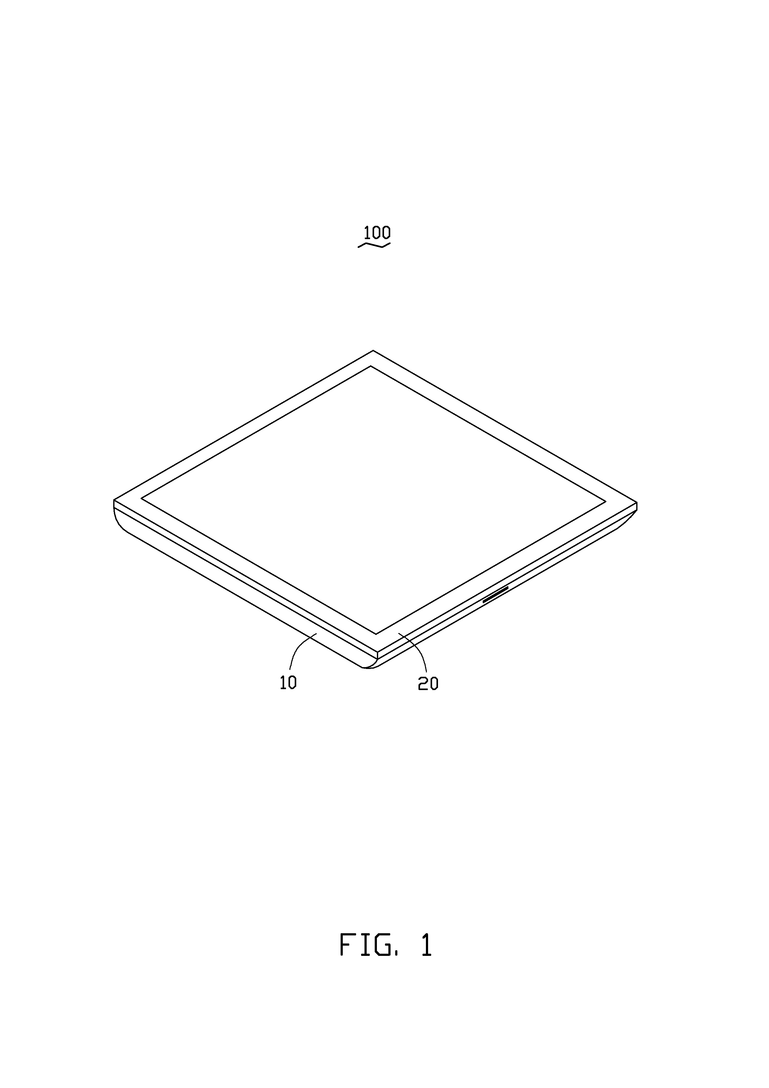
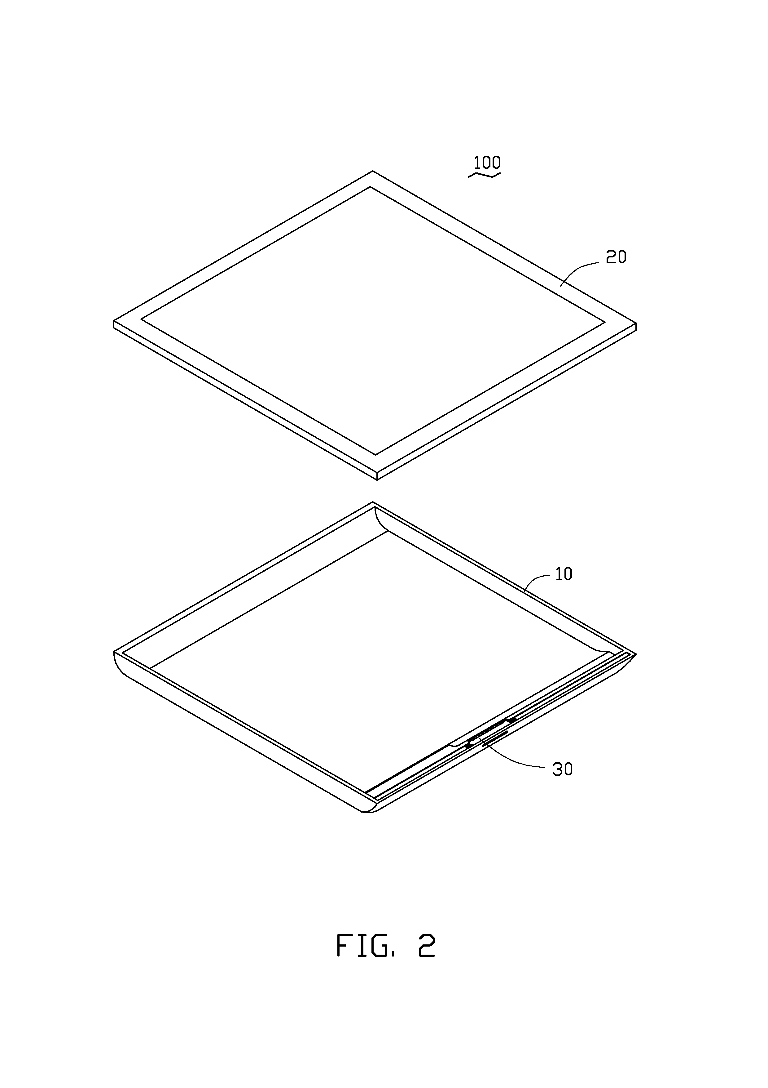
[0014]Referring to FIGS. 1 and 2, an embodiment of an electronic device 100 is shown. The electronic device 100 includes a housing 10, a cover 20 covered on the housing 10 and a connector assembly 30 mounted at the housing 10. In the illustrated embodiment, the electronic device 100 is a tablet computer. The electronic device 100 also includes various other functional modules for performing specific functions which are not described herein for the sake of simplicity.

[0015]Also referring to FIG. 3 through FIG. 5, the housing 10 is a hollow structure. The housing 10 includes a bottom wall 11 and a sidewall 13 extending from edges of the bottom wall 11. The sidewall 13 includes an outer side surface 131, a top surface 133 and an inner side surface 135. The top surface 133 connects with the outer side surface 131 and the inner side surface 135. The outer side surface 131 is a smooth curved surface. The top surface 133 is a planar surface. The top surface 133 is parallel to the bottom wa...


PUM


Abstract

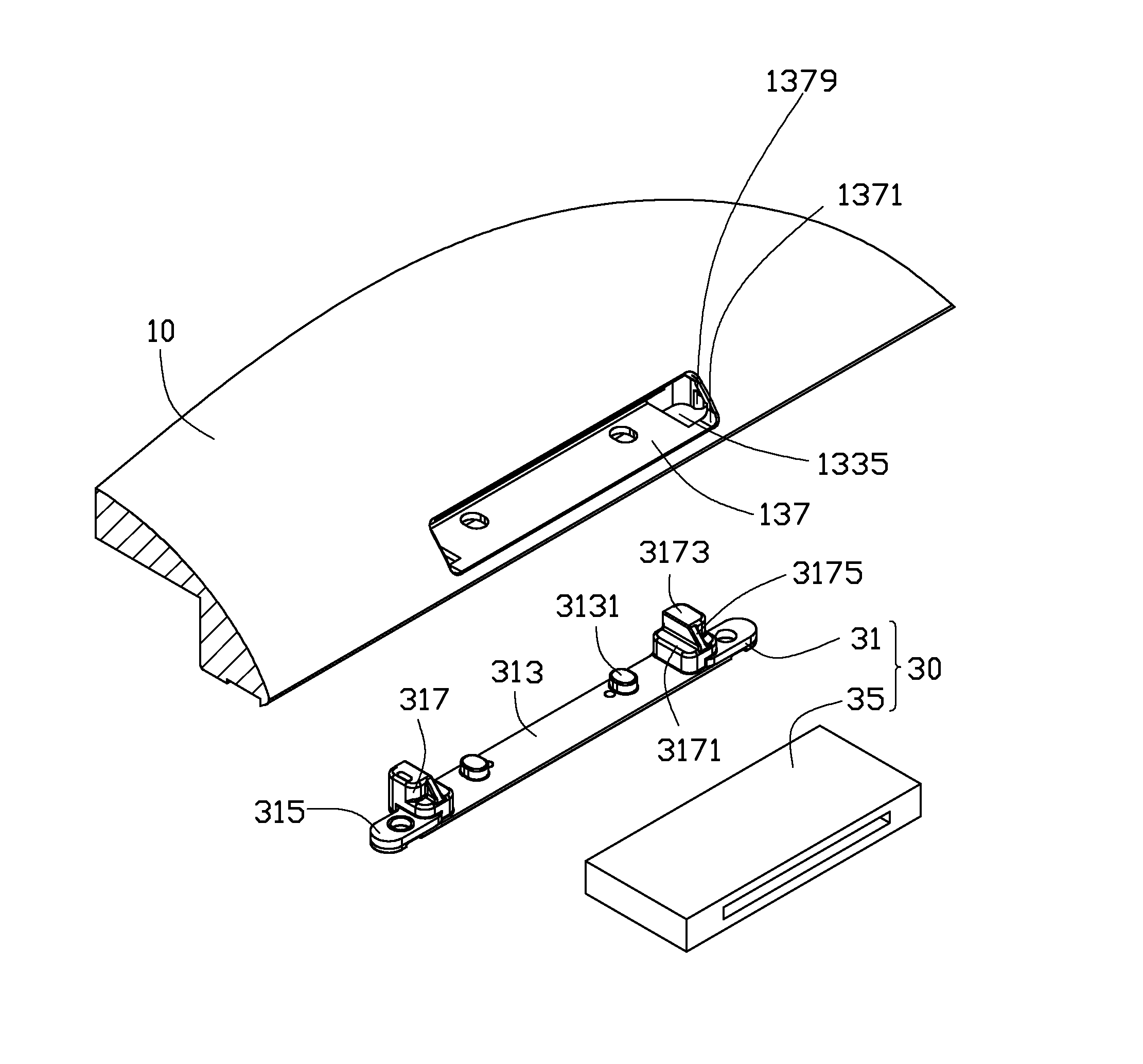
An electronic device includes a housing and at least one connector assembly. The housing includes a bottom wall and a sidewall. The sidewall includes an outer side surface, a top surface and an inner side surface. At least one insertion interface is defined through the outer side surface. One resisting groove is defined on each end wall of the insertion interface. The top surface forms at least one receiving groove communicating with the corresponding insertion interface. Each connector assembly includes a connecting member and a connector. The connecting member includes a main body and two positioning ends protruding from the main body. The main body is received in the receiving groove. Each positioning end passes through the receiving groove and extends into the insertion interface to resist a side wall of one resisting groove. The connector is received in the insertion interface and resists between the two positioning ends.

Description

BACKGROUND[0001]1. Technical Field[0002]The present disclosure generally relates to electronic devices, and particularly to an electronic device having connector assemblies for transmitting data with other electronic devices.[0003]2. Description of Related Art[0004]Electronic devices, such as mobile phones, tablet computers, and media players, may have several connecting interfaces for inserting connectors of external devices for the transmission of data. Universal Serial Bus (USB) connectors are one of the most current connectors available. Support modules are positioned in the electronic devices and are electrically connected to the USB connecters. A USB connector positioned in the electronic device will be electrically connected to the support module via a connecting port positioned on the housing. It may be difficult to accurately position the connecting port in an electronic device because of the small size and reduced height of the connecting port. In addition, the USB connect...

Claims


Application Information

Patent Timeline
Patent Type & Authority Applications(United States)
IPC IPC(8): H05K7/00
CPCH01R13/74G06F1/1656H01R2201/06
Inventor DUAN, JU-PINGLUO, MING-FU
Owner FU TAI HUA IND SHENZHEN
Learn More