Electrical connector, electronic apparatus using the same, and assembling method of the electrical connector

a technology of electrical connectors and connectors, which is applied in the direction of electrical apparatus, two-part coupling devices, and coupling device connections, etc., can solve the problems of increased manufacturing costs, reduced product yield, and high manufacturing costs, and achieves improved contact elasticity, preventing damage to the terminal structure, and simplifying the insulation body structure

Inactive Publication Date: 2013-07-18
ANT PRECISION IND CO LTD
View PDF6 Cites 6 Cited by
  • Summary
  • Abstract
  • Description
  • Claims
  • Application Information

AI Technical Summary

Benefits of technology

[0025]Each terminal structure includes an elastic contact section and at least one elastic/non-elastic support section. When corresponding terminals of a complementary electrical connector electrically contacts against the elastic contact section, the at least one elastic/non-elastic support section can provide better contact elasticity by produc...

Problems solved by technology

However, this type of complicated and small-dimensional structure would not only require the use of many different molds to manufacture, the assembly tolerance and the difficulties involved in the assembling process would also be increased and cause the product yield to be decreased, which results in higher manufacturing costs.
In this manner, when corresponding terminals of a complementary electrical connector is inserted into the conventional USB 3.0 electrical connectors to press against another c...

Method used


Image

  • Electrical connector, electronic apparatus using the same, and assembling method of the electrical connector
  • Electrical connector, electronic apparatus using the same, and assembling method of the electrical connector
  • Electrical connector, electronic apparatus using the same, and assembling method of the electrical connector

Examples


first embodiment

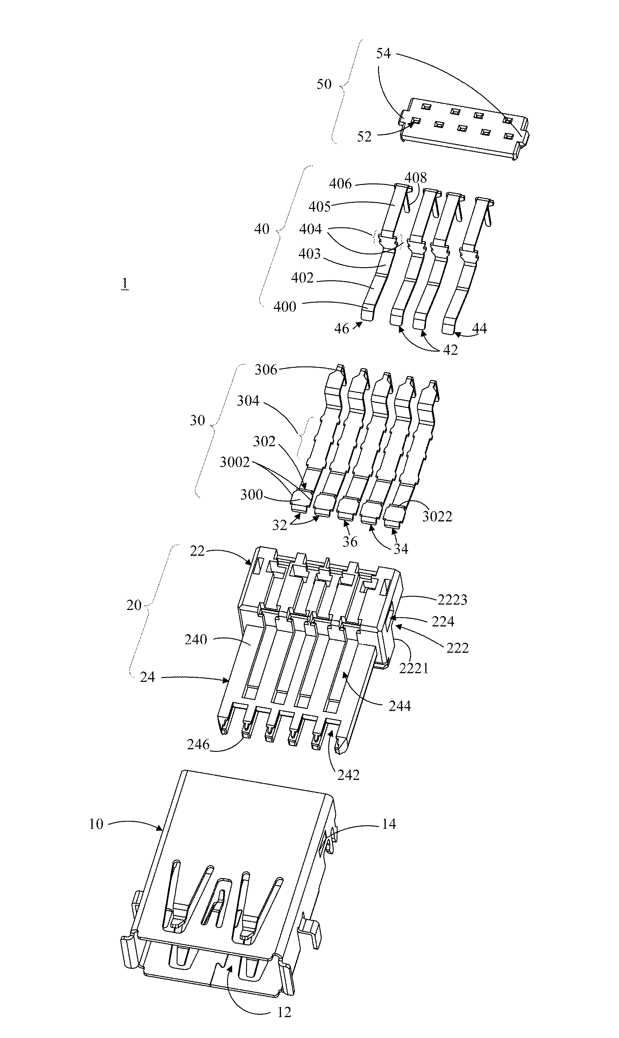
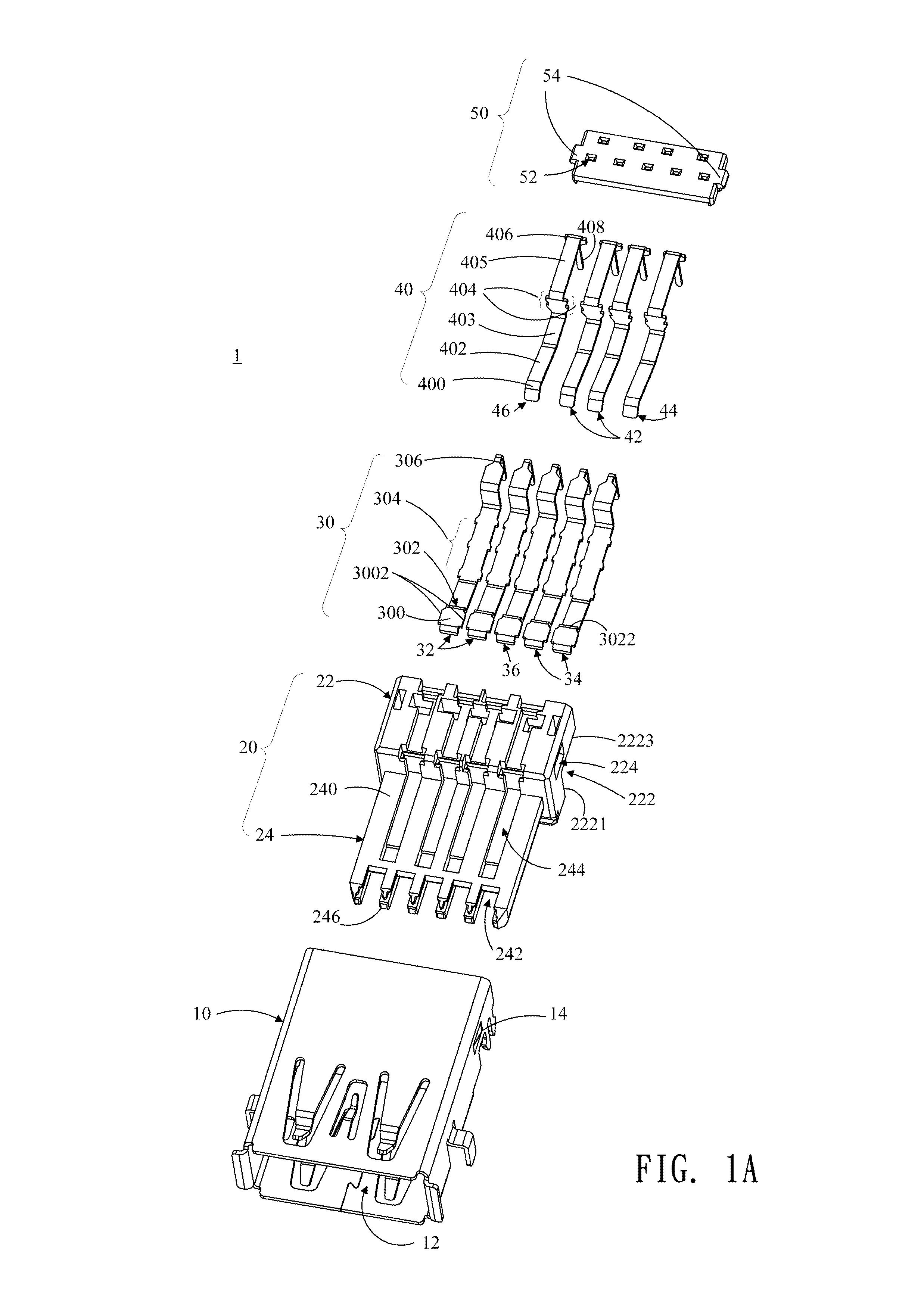
[0037]Please refer to FIG. 1A, which illustrates an electrical connector 1 of the present invention that complies with the USB 3.0 signal transmission stands and is used for electrically connection with a complementary electrical connector (not shown). The electrical connector 1 primarily includes a shielding housing 10, an insulation body 20, a first terminal set 30, a second terminal set 40, and a positioning part 50.

[0038]The shielding housing 10 primarily is formed from four wall surfaces, wherein an accommodating space 12 is formed within the confines of the four wall surfaces for accommodating the insulation body 20. A hook 14 is formed recessing inwards on the left and right wall surfaces of the four wall surfaces.

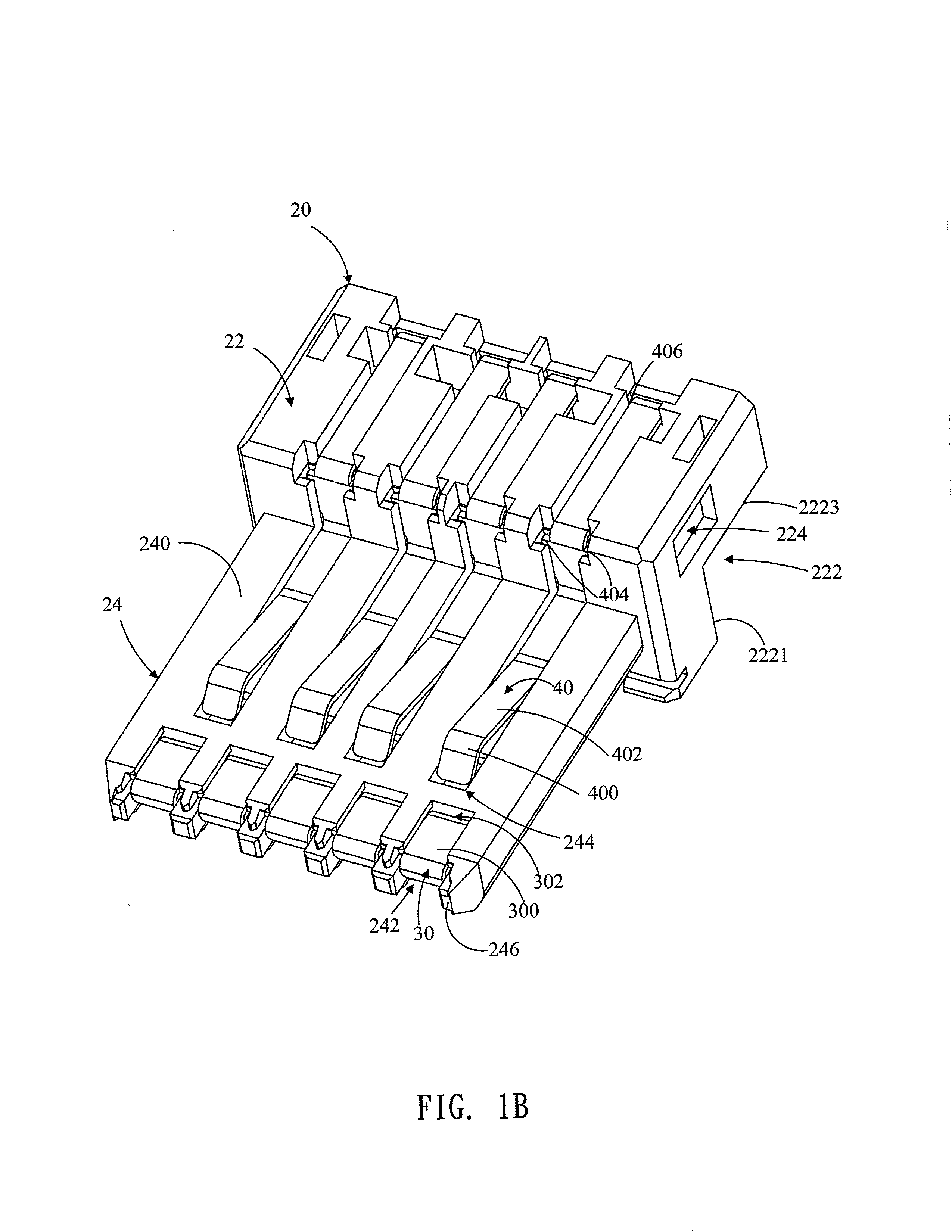
[0039]As shown in FIGS. 1A and 1B, in the present embodiment, the entire body of the insulation body 20 is manufactured and formed as a unitary structure with plastic materials. The insulation body 20 includes a base part 22 and a mating part 24, wherein a recessed ...

seventh embodiment

[0053]FIG. 8 illustrates an eight embodiment of the electrical connector 8. In comparison to the electrical connector 7 of the seventh embodiment, the first terminal set 30 of the electrical connector 8 also includes an elastic slice section 3004 that is punched or stamped upward in the elastic contact section 300 such that a bend 3009 is formed at the connection between the elastic slice section 3004 and the elastic contact section 300. The elastic slice section 3004 extends towards but not overpasses the mating surface 240 of the insulation body 20. In this manner, the elastic movement distance D4 may be increased (i.e. D4>D3) such that higher contact elasticity may be provided when the electrical connector 8 is plugged.

[0054]According to another embodiment of the present invention, an electronic device is provided with the mentioned embodiments of the electrical connector 1, 2, 3, 4, 5, 6, 7, and 8 installed therein. The electronic device may include laptop computers, tablet comp...

ninth embodiment

[0062]From a back to front direction, the first terminal set 30 is respectively inserted and disposed into the plurality of first terminal set passages 242 from the back end of the insulation body 20 (i.e. at the vertical wall surface 2221 of the recessed portion 222 opposite the front end 246). Then, the holding section 304 is fixed in the first terminal set passage 242 below the insulation body 20, wherein the position of the elastic contact section 300 of the first terminal set 30 is distributed on the mating surface 240 of the mating part 24 close to the front end 246. In this instance, the elastic contact section 300 of the first terminal set 30 is accommodated in the slit 2465 of the first terminal set passage 242. The two wing sections (not shown) of the elastic contact section 300 lies between the upper blocker 2461 and the lower blocker 2463 within the first terminal set passage 242. At least one bend 3032 formed at the connection between the elastic contact section 300 and...


PUM


Abstract

An electrical connector, an electronic apparatus using the same, and an assembling method of the electrical connector are introduced herein. The electrical connector includes first set terminals, second set terminals, and an insulated housing which has a plurality of first set terminal passages and second set terminal passages for respectively disposing said first and second terminals therein. When an elastic contact section of the respective first set terminal contacts with a complementary electrical connector, at least one elastic supporting section of the respective first set terminal provides flexibility required for the elastic contact section so that the elastic contact section can limitedly and elastically move within the corresponding first set terminal passage

Description

BACKGROUND OF THE INVENTION[0001]1. Field of the Invention[0002]The present invention generally relates to an electrical connector, an electronic apparatus using the same, and an assembling method of the electrical connector; particularly, the present invention relates to a terminal structure of an electrical connector having better contact elasticity.[0003]2. Description of the Related Art[0004]Presently, the development of signal transmission standards of Universal Serial Bus (USB) has reached USB version (3.0). Electrical connectors in compliance with USB 3.0 standards not only can selectively electrically connect a USB 3.0 complementary electrical connector, but may also selectively electrically connect electrical connectors in compliance with USB 1.0 / 2.0 standards so that signal transmissions complying with the USB 1.0 / 2.0 standards may be conducted. In order to allow the USB 3.0 electrical connector to be compatible with USB 1.0 / 2.0 standards, the USB 3.0 electrical connector ...

Claims


Application Information

Patent Timeline
IPC IPC(8): H01R24/60
CPCH01R24/60H01R24/62H01R13/2442
Inventor HSUEH, CHIH-YU
Owner ANT PRECISION IND CO LTD
Why Eureka
Try Eureka