
Automatic network design

Inactive Publication Date: 2013-07-18
CONSISTEL PTE
View PDF5 Cites 28 Cited by
  • Summary
  • Abstract
  • Description
  • Claims
  • Application Information

AI Technical Summary

Benefits of technology

The patent is about a method that allows users to easily and quickly design wireless networks for different types of mobile devices. It is designed to be a powerful tool for creating efficient and low-cost networks in both indoor and outdoor areas.

Problems solved by technology

One important issue is the location and number of antennas.
A problem with network design methods of the prior art is that minimum cost and optimal placement are not guaranteed.
Additionally, there are no methods for automatic determination of antenna numbers and locations by mathematic analysis for 2G Global System for Mobile Communications (GSM), 3G Wideband Code Division Multiple Access (WCDMA) or Code Division Multiple Access 2000 (CDMA2000), or 4G 3GPP Long Term Evolution (LTE), Wireless Fidelity (WiFi), and Worldwide Interoperability for Microwave Access (WiMAX) network component multi-service wireless network design.
Yet a further problem is that many of the methods of the prior art are limited to outdoor wireless network design.

Method used


Image

  • Automatic network design
  • Automatic network design
  • Automatic network design

Examples


Embodiment Construction

[0087]Embodiments of the present invention comprise network planning methods. Elements of the invention are illustrated in concise outline form in the drawings, showing only those specific details that are necessary to the understanding of the embodiments of the present invention, but so as not to clutter the disclosure with excessive detail that will be obvious to those of ordinary skill in the art in light of the present description.

[0088]In this patent specification, adjectives such as first and second, left and right, front and back, top and bottom, etc., are used solely to define one element or method step from another element or method step without necessarily requiring a specific relative position or sequence that is described by the adjectives. Words such as “comprises” or “includes” are not used to define an exclusive set of elements or method steps. Rather, such words merely define a minimum set of elements or method steps included in a particular embodiment of the present...


PUM


Abstract

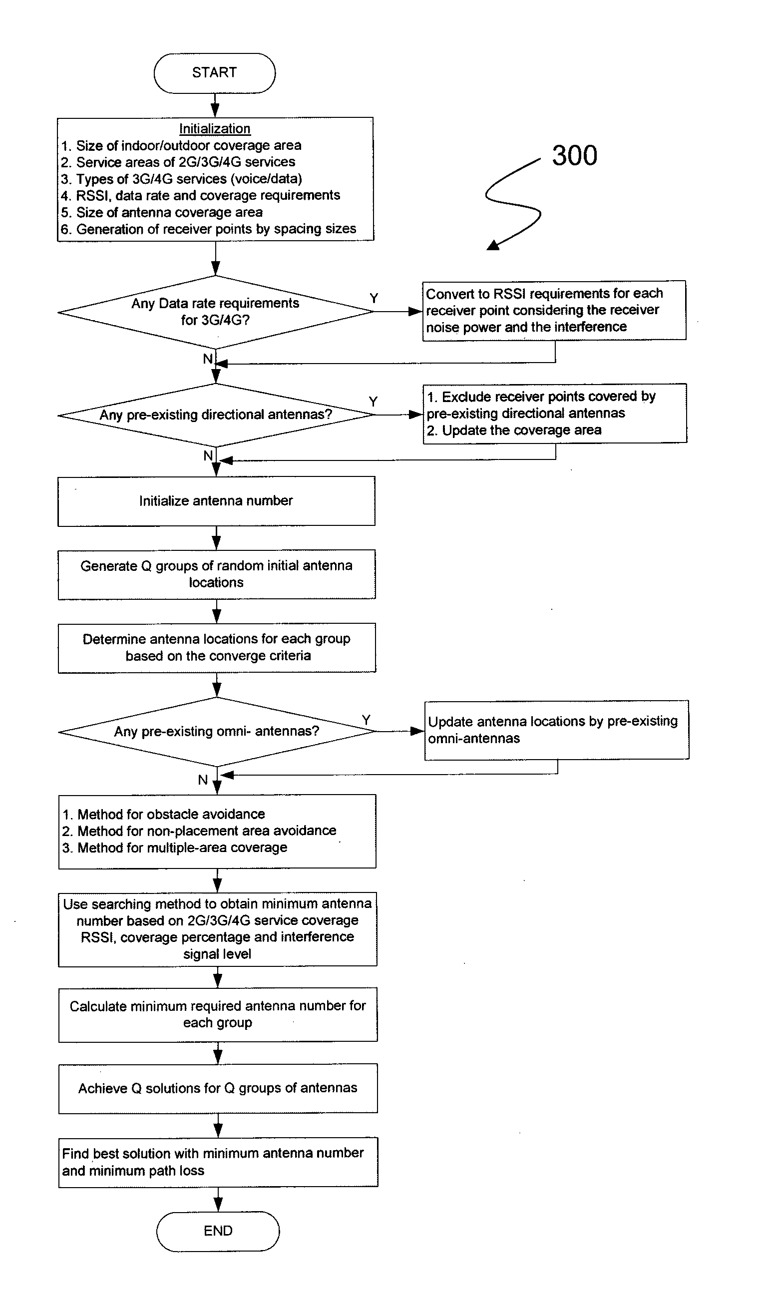
A method and system for communication network design, the method including: generating, by a computer processor, a plurality of receiver points; generating a target received signal strength for each receiver point of the plurality of receiver points; determining a predicted number of antennas based on a size of the communications network and a coverage area of an antenna; determining a location for each antenna of the predicted number of antennas; generating an estimated received signal strength for each receiver point of the plurality of receiver points, based upon the predicted number of antennas and the location of each antenna of the predicted number of antennas; comparing the estimated received signal strength for each receiver point with the target received signal strength for the receiver point; generating a revised predicted number of antennas based upon at least one of the comparisons of target received signal strength and estimated received signal strength.

Description

FIELD OF THE INVENTION[0001]The present invention generally relates to automatic network design. In particular, although not exclusively, the invention relates to a method for automatic determination of antenna numbers and locations.BACKGROUND OF INVENTION[0002]Intensive research interests have been in larger capacity and less transmission power of wireless handsets over wireless network design. One way to meet these requirements is to shrink the cell sizes and increase the number of cells. One important issue is the location and number of antennas.[0003]Several patents relating to antenna placement are listed below:[0004][1]. Patent No WO0225506A1 entitled “Method and system for automated selection of optimal communication network equipment model, position and configuration in 3-D” by Rappaport Theodore, Skidmore Roger and Sheethalnath Praveen, 2002.[0005][2]. Patent No WO0227564A1 entitled “System and method for design, tracing, measurement, prediction and optimization of data com...

Claims


Application Information

Patent Timeline
IPC IPC(8): H04W16/18
CPCH04W16/18H04W16/20H04W24/10
Inventor BASSIRI, MASOUDZHANG, HUACAMPBELL, DUNCAN KARL GORDONFORUGHIAN, TOORAJDANIEL, NEIL
Owner CONSISTEL PTE
Learn More