Digital wireless network receptacle

a wireless network and receptacle technology, applied in the direction of protective switches, instruments, and device connections, can solve the problems of ten percent of regular household power consumption wasted, insufficient space in the receptacle to accommodate the overall size of the intelligent chip module, and the chance of electrical appliances failing to be monitored half a chan

Inactive Publication Date: 2013-07-18
TING ROY +2
View PDF8 Cites 24 Cited by
  • Summary
  • Abstract
  • Description
  • Claims
  • Application Information

AI Technical Summary

Benefits of technology

[0006]An objective of the present invention is to provide a digital wireless network receptacle having a single microcontroller unit (MCU) mounted therein to independently monitor each socket of the receptacl...

Problems solved by technology

According to studies, ten percent of regular household power usage is wasted, mostly occurring when corresponding electrical appliances are in a standby state instead of an operating state.
If two intelligent chip modules are simultaneously mounted in a receptacle, the receptacle has insufficient space to accommodate the overall size of the intelligent chip modules, let alone related metal pins necessarily mounted inside the receptacle.
Since each digital wireless ...

Method used


Image

  • Digital wireless network receptacle
  • Digital wireless network receptacle
  • Digital wireless network receptacle

Examples


Embodiment Construction

[0027]It is to be noted that the following descriptions of preferred embodiments of this invention are presented herein for purpose of illustration and description only; it is not intended to be exhaustive or to be limited to the precise form disclosed.

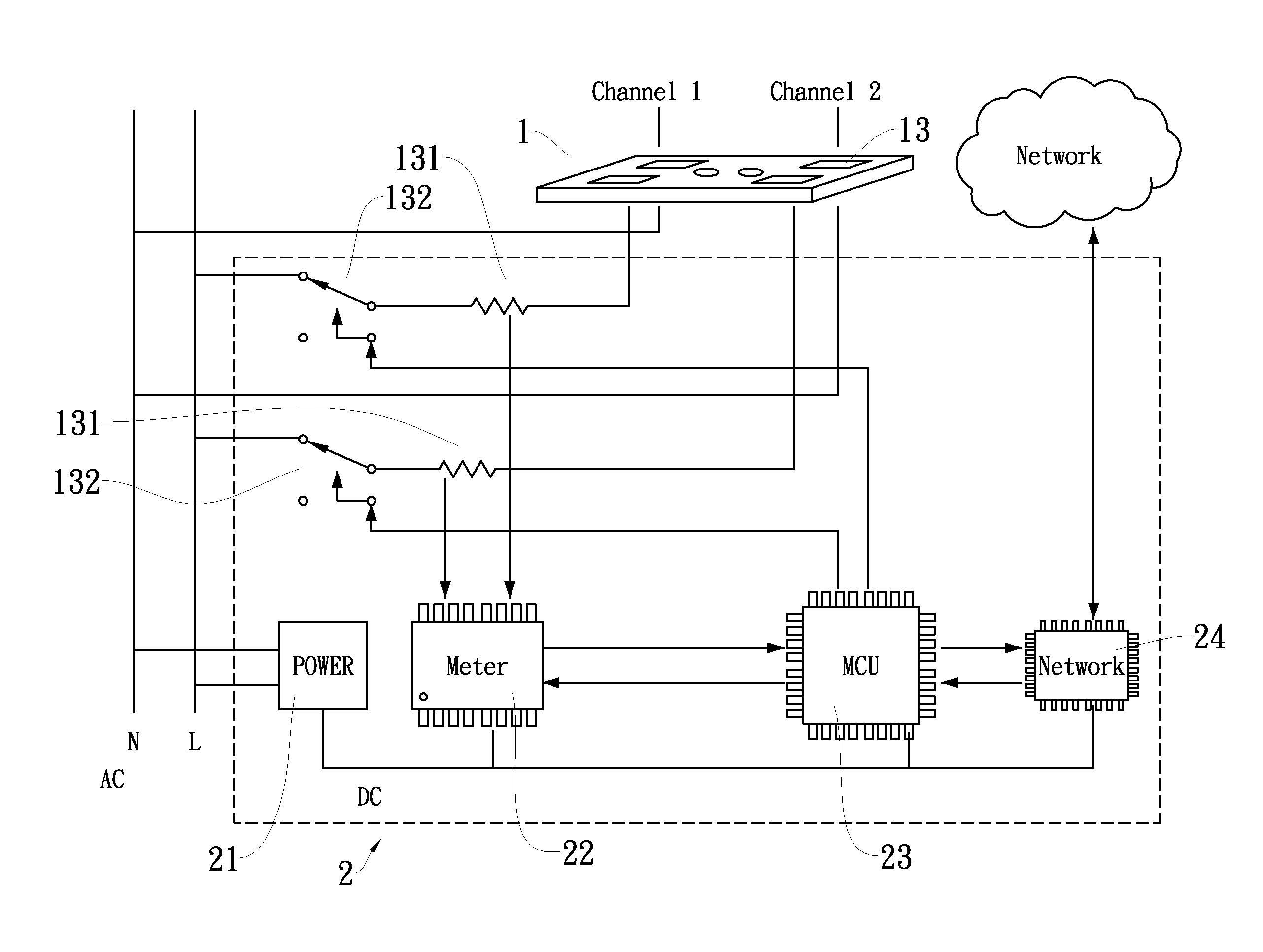
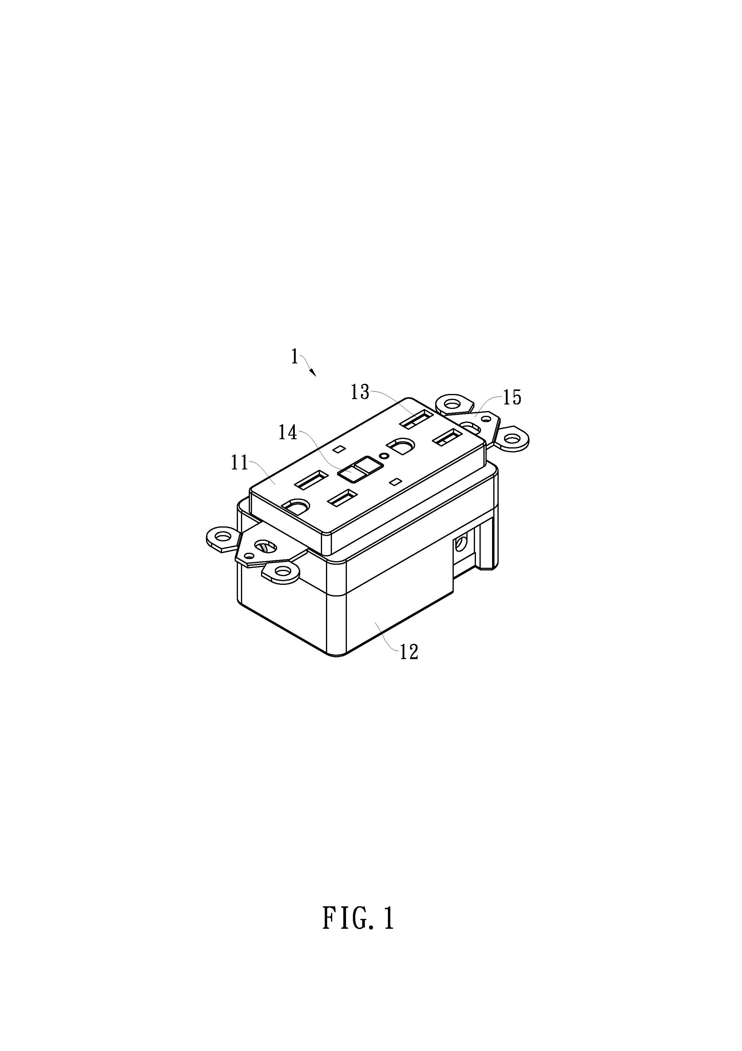
[0028]The structure and applications of the present invention will now be described more specifically with reference to the following embodiments. With reference to FIGS. 1 to 3, a digital wireless network receptacle (DWNR) 1 in accordance with the present invention has an upper housing 11, two power sockets 13, a lower housing 12 and a multi-layer mechanism 10.

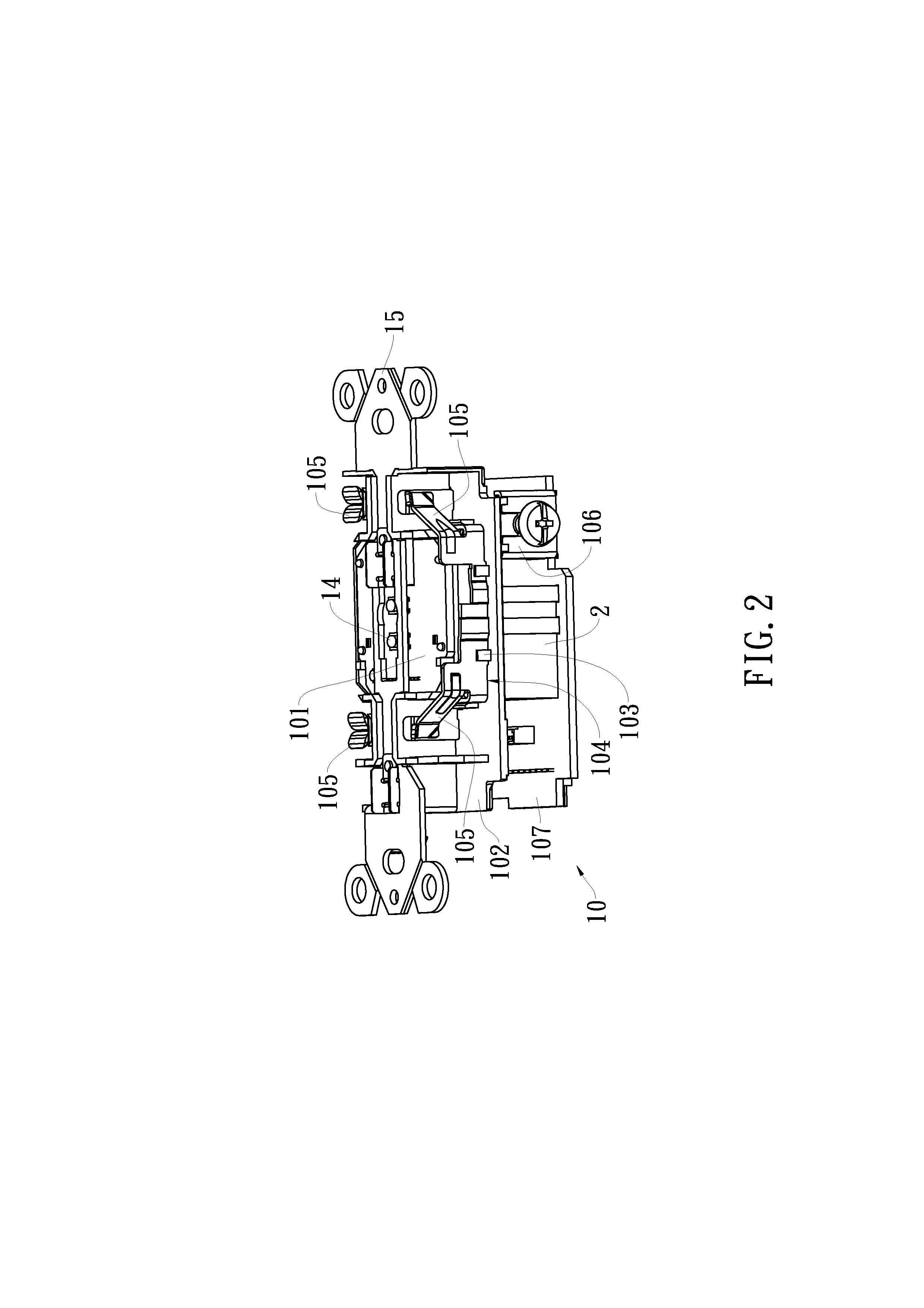
[0029]The power sockets 13 are formed through the upper housing 11 and each power socket 13 has two inner terminals. The multi-layer mechanism 10 is mounted between the upper housing 11 and the lower housing 12 and has a top platform 101, a middle layer 102 and a bottom plate 107. The top platform 101 has at least one reset buttons 14 and two lugs 15. In the present embodiment,...


PUM


Abstract

A digital wireless network receptacle has an upper housing, two power sockets formed through the upper housing, a lower housing and a multi-layer mechanism mounted between the upper housing and the lower housing. A single microcontroller unit (MCU) is employed within the multi-layer mechanism so that an intelligent control circuit can be effectively integrated and received in the receptacle with standardized size and limited space. Each power socket of the receptacle is independently monitored and controlled, and power consumed from each power socket can be recorded to ensure a complete understanding of power usage. Besides transmission of power consumption information to a host server through a wireless network, automatic power breaking safety protection upon an overload or standby condition of electrical appliances can be provided.

Description

FIELD OF THE INVENTION[0001]The present invention relates to a digital wireless network receptacle and more particularly to a digital wireless network receptacle having a single microcontroller unit (MCU) mounted therein to independently monitor each power socket of the receptacle, measure power consumed from each power socket, collect power consumption information through a wireless network, and provide automatic power breaking safety protection upon an overload or standby condition of electrical appliances.BACKGROUND OF THE INVENTION[0002]In view of the increasingly aggravated energy shortage crisis, energy conservation and environmental protection issues are reaching a global consensus. According to studies, ten percent of regular household power usage is wasted, mostly occurring when corresponding electrical appliances are in a standby state instead of an operating state.[0003]Fortunately, newly developed intelligent chip modules can be built in home electrical appliances to sig...

Claims


Application Information

Patent Timeline
IPC IPC(8): G06F1/32G06F1/28H02J3/00
CPCH02J3/00H01H2071/008H01R13/6683H01R24/78H02J13/0075H02J3/14H02H3/40H02H3/006H02H3/00H02M2001/0009H01H2071/006G06F1/3287G06F1/3203H02J13/0086G01R21/133Y04S40/126Y04S20/222Y02B70/3225Y02B90/20H02M1/0009
Inventor LI, MAXTING, ROY
Owner TING ROY
Why Eureka
Try Eureka