Looped Bungee Strap Tie-Down with Locking Slide

a bungee strap and slide technology, applied in the direction of snap fasteners, buckles, mechanical devices, etc., can solve the problems of relative weak holding power, and achieve the effect of secure grasping and tensioning, easy adjustment of loops, and quick adjustment of loops

Inactive Publication Date: 2013-07-25
CAMPBELL PHILLIP R
View PDF0 Cites 36 Cited by
  • Summary
  • Abstract
  • Description
  • Claims
  • Application Information

AI Technical Summary

Benefits of technology

[0016]The preferably two piece slide comprises a mated pair of complementary halves, each shaped like a hemisphere. Parallel and spaced apart channels within each half register in assembly to form a pair of parallel passageways through which the cord extends. The diameter of each channel is less than the rest diameter of the cord; in other words, without stretching the cord, the cord's diameter exceeds the diameter of the slide passageways. Each channel and each passageway has a plurality of spaced-apart, internal nubs that frictionally contact the cord. The nubs frictionally engage the cord when the cord is relaxed to restrain the slide. Relaxation of the cord insures that the expanded cord diameter will contact the nubs, and the cord will be firmly, frictionally restrained within the slide. When the cord is longitudinally stretched, the resulting decreased cord diameter will relieve interference between the cord, the passageways, and the nubs, and movement of the slide will be facilitated.
[0017]Thus a basic object is to provide an easily adjustable bungee-type strap or tie-down for fastening various diverse articles or bundles of various miscellaneous items.
[0019]Another important object is to provide a slide mechanism for looped fastener straps that quickly adjusts the loop and securely grasps and tensions it.
[0020]A related object is to provide a cord lock which is adapted to secure two portions of an elastic cord therein such that the cords portions remain in position without slippage during use.

Problems solved by technology

Some known straps include a pair of spherical elements, one comprising an anchor, and the other functioning as a slide, but hitherto these have been unreliable.
Notwithstanding the relatively abundant prior art, tie-downs having sliding components associated with bungee-type cords have hitherto demonstrated relative weak holding power.

Method used


Image

  • Looped Bungee Strap Tie-Down with Locking Slide
  • Looped Bungee Strap Tie-Down with Locking Slide
  • Looped Bungee Strap Tie-Down with Locking Slide

Examples


Embodiment Construction

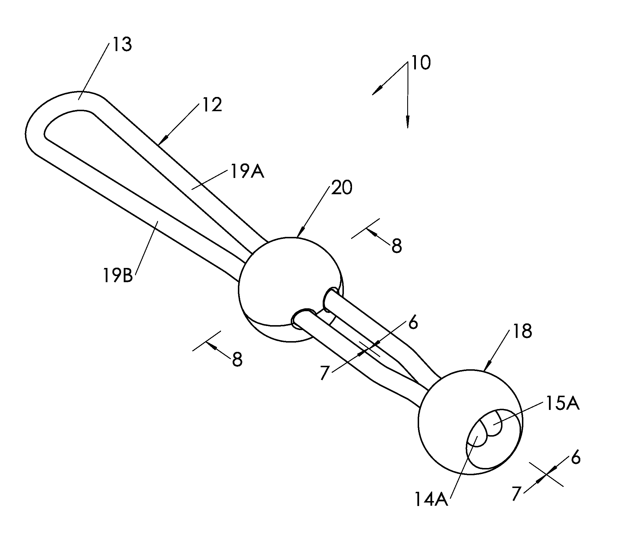
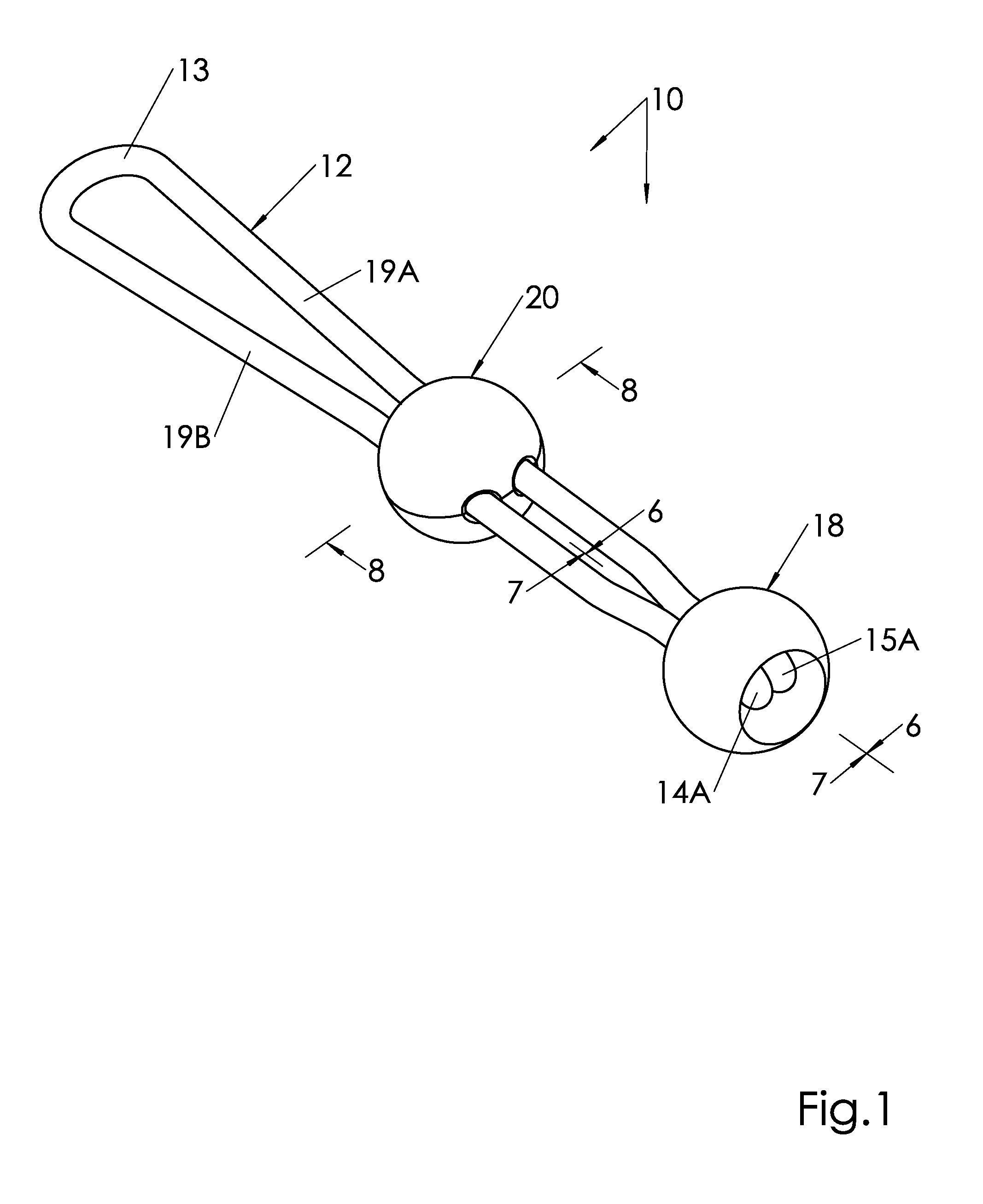
[0035]With initial reference directed to FIGS. 1-3 of the appended drawings, a looped bungee-cord type fastener constructed generally in accordance with the best mode of the invention has been generally designated by the reference numeral 10. The fastener 10 is user adjustable so it can be readily adapted for a variety of applications. It can be stretched to fit around a variety of differently sized items, and it can be used in various situations involving different dimensions.

[0036]Preferably, fastener 10 comprises an elongated, elastic bungee-type cord 12 that is folded at one end, forming a loop 13. The opposite terminal ends 14, 15 (FIG. 7) of the cord 12 form terminal anchor loops 14A, 15A that are secured and locked within a hollowed anchor 18, as explained in detail hereinafter. Parallel, elongated cord portions 19A, 19B of the cord 12 extend from the looped end 13 through an adjustable slide 20 to the ends 14 and 15 (FIG. 7).

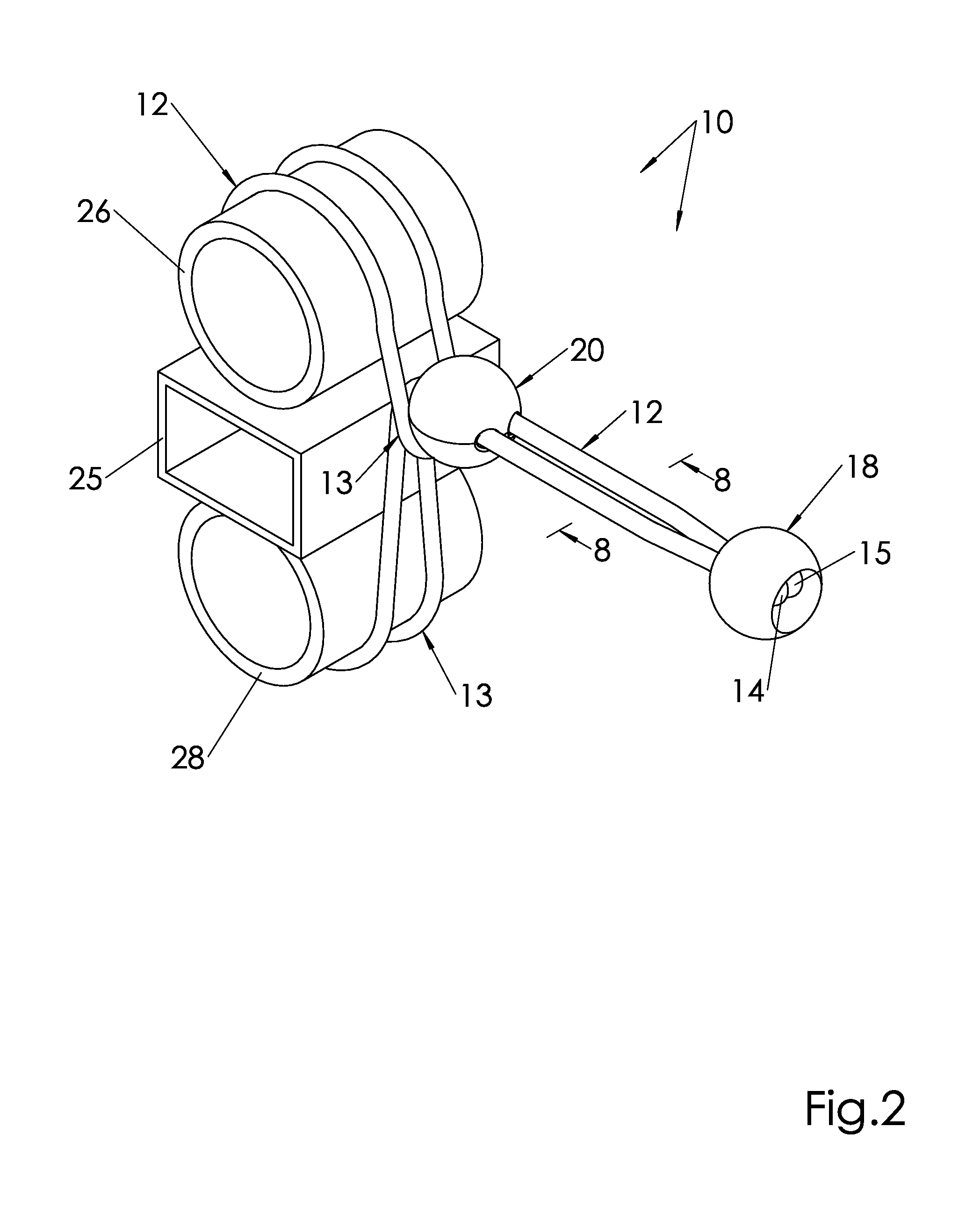
[0037]FIG. 2 illustrates generally how the cord ca...


PUM


Abstract

A looped bungee cord fastener strap exerts extreme force to temporarily hold and restrain a variety of differently sized and shaped objects. An elongated cord has terminal ends restrained and shrouded within a spherical anchor that are integral with a spaced apart loop in the cord. The cord a two-piece spherical slide sized like the anchor formed from a pair of complementary halves. The cord extends through parallel passageways in the spherical slide, and when the cord is stretched, the slide can be displaced relative to the cord. Each slide passageway has a plurality of spaced-apart, internal nubs that frictionally contact the cord when it is unstretched to lock the slide and cord relative to each other. Surface segments adjacent the passageways in each slide half, and wall surfaces between passageways in each half, contact one another in assembly for strength.

Description

BACKGROUND OF THE INVENTION[0001]1. Field of the Invention[0002]The present invention relates generally to stretchable tie-downs cords. More particularly, the present invention relates to adjustable, looped, bungee-cord fasteners with slidable components. Known prior art of this general type is classified in United States Patent Class 24, Subclasses 115 and 136.[0003]2. Description of the Related Art[0004]A variety of bungee cords, tie-downs, and fastener straps are well known in the art. Some known straps include a pair of spherical elements, one comprising an anchor, and the other functioning as a slide, but hitherto these have been unreliable. Usually, after moderate use, the cord ceases to frictionally lock the slide, so the cord's efficiency is sacrificed.[0005]U.S. Pat. No. 3,965,544 issued Jun. 29, 1976 discloses a slidable cord locking device Having a slide received within a tapered passage. A cord extends along a path between a locking portion of the slide and a side wall o...

Claims


Application Information

Patent Timeline
Patent Type & Authority Applications(United States)
IPC IPC(8): F16G11/12
CPCF16G11/101Y10T24/316F16G11/14
Inventor CAMPBELL, PHILLIP R.
Owner CAMPBELL PHILLIP R
Why Eureka
Try Eureka