
Communication and control of accessories mounted on the powered rail of a weapon

a technology of communication and control system and powered rail, which is applied in the direction of weapons, firing/trigger mechanisms, butts, etc., can solve the problems of inconvenient power-consuming accessories, power-consuming accessories that cannot be quickly powered up and down, and the power-consuming accessories are inconvenient for users to us

Active Publication Date: 2013-07-25
T WORX HLDG LLC
View PDF8 Cites 60 Cited by
  • Summary
  • Abstract
  • Description
  • Claims
  • Application Information

AI Technical Summary

Benefits of technology

The present invention relates to a system for controlling accessories attached to a weapon, such as a military weapon, that have a powered rail. The system allows the user to control the activation of the accessory from a central control interface. The system also facilitates communication between the user, the accessories, and other accessories, even without a central control apparatus. The technical effect is improved control and communication for accessories attached to a weapon.

Problems solved by technology

It is a problem to distribute command and control signals to power-consuming accessories, which are operationally associated with a weapon and attached to the weapon's Powered Rail, that electrically connects the power-consuming accessories to a centrally located power source.
However, a Powered Rail by itself fails to provide a user with control over the operation of the power-consuming accessories, since it simply provides an electrical connection to the power source and must rely on a power switch mounted on each power-consuming accessory to enable the user to apply power in a binary, on / off manner to that power-consuming accessory.
The need to operate such a switch on a power-consuming accessory is inconvenient and prevents the user from having the ability to rapidly power-up and power-down the power-consuming accessory.
In the case of a plurality of power-consuming accessories being mounted on the weapon, such a power control method is cumbersome at best.

Method used


Image

  • Communication and control of accessories mounted on the powered rail of a weapon
  • Communication and control of accessories mounted on the powered rail of a weapon
  • Communication and control of accessories mounted on the powered rail of a weapon

Examples


Embodiment Construction

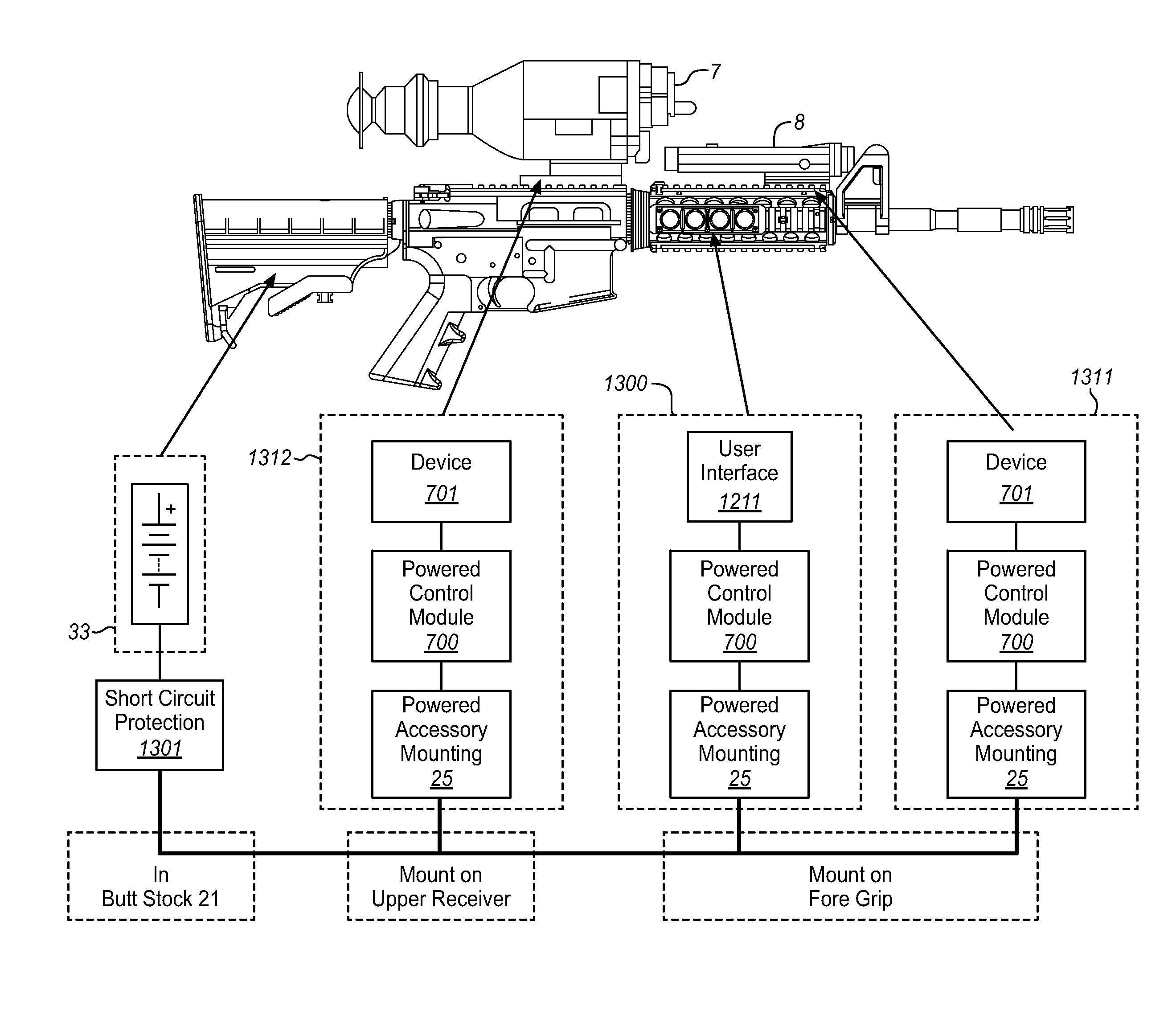
[0018]The use of a Powered Rail on a weapon serves multiple types of power-consuming accessories such as: tactical lights, laser aiming modules, night vision devices, and reflex sights. The Powered Rail can be incorporated on the top, bottom, or sides of the rifle barrel, the underside of semi-automatic pistol frames, and even on weapon grips. Regardless of the location and implementation of the Powered Rail, the problem of control and communication with and among the power-consuming accessories is a universal issue.

Weapon Equipped With Weapon Accessory Power Distribution System

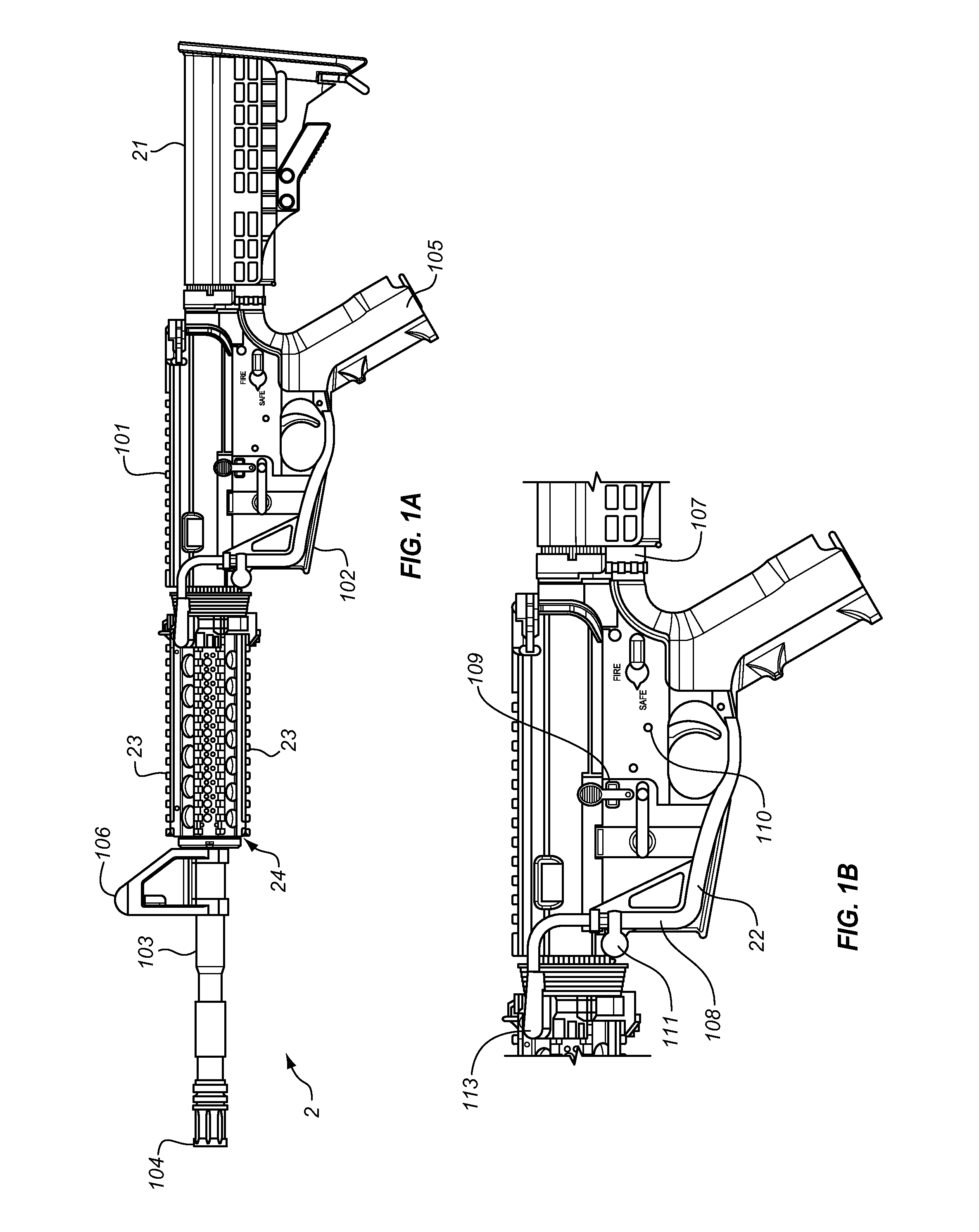
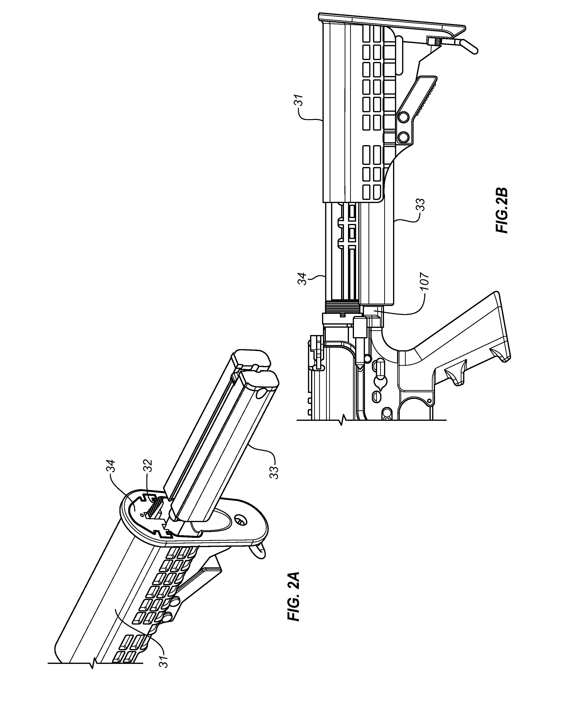
[0019]FIGS. 1A and 1B are illustrations of the system architecture of a military style weapon 2 equipped with a Weapon Accessory Power Distribution System. The primary components of the basic Weapon Accessory Power Distribution System are:[0020]Butt Stock 21 with Battery Pack 33 (shown in FIG. 2A);[0021]Power Distribution System 22;[0022]Handguard 23 (optional);[0023]Powered Rail 24; and[0024]Powered Accessor...


PUM


Abstract

A firearm used in military applications may have a plurality of accessories that can be attached to the weapon, with each accessory having a need for electric power. In order to reduce the weight of these power-consuming accessories, as well as the proliferation of batteries used to power these power-consuming accessories, a Powered Rail provides a point of mechanical and electrical interconnection for the power-consuming accessories with a common power source. The Weapon Accessory Control System is provided to enable the user to control the activation of a power-consuming accessory as well as enable communications between the user and the power-consuming accessory and among power-consuming accessories.

Description

STATEMENT REGARDING FEDERALLY SPONSORED RESEARCH OR DEVELOPMENT[0001]This application is sponsored by the US Department of Defense under Contract Numbers W15QKN-08-C-0072 and W15QKN-09-C-0045.FIELD OF THE INVENTION[0002]The invention relates to a communications and control system for use with a Powered Rail of a weapon to provide communications and control signals as well as electric power to power-consuming accessories mounted on the Powered Rail.BACKGROUND OF THE INVENTION[0003]It is a problem to distribute command and control signals to power-consuming accessories, which are operationally associated with a weapon and attached to the weapon's Powered Rail, that electrically connects the power-consuming accessories to a centrally located power source. A weapon used in military applications may have a plurality of accessories that can be attached to the weapon, with each accessory having a need for electric power. In order to reduce the weight of these power-consuming accessories, a...

Claims


Application Information

Patent Timeline
IPC IPC(8): F41C27/00
CPCF41C23/22F41G11/003
Inventor DODD, JAMES S.FELDMAN, BENMILLER, TYLERJORDAN, TERRANCEPAULSEN, GREG
Owner T WORX HLDG LLC
Features
  • Generate Ideas
  • Intellectual Property
  • Life Sciences
  • Materials
  • Tech Scout
  • Unparalleled Data Quality
  • Higher Quality Content
  • 60% Fewer Hallucinations
Learn More