Dual fuel aircraft system and method for operating same

a dual fuel, aircraft technology, applied in the field of aircraft systems, can solve the problem of low engine efficiency

Inactive Publication Date: 2013-07-25
GENERAL ELECTRIC CO
View PDF18 Cites 26 Cited by
  • Summary
  • Abstract
  • Description
  • Claims
  • Application Information

AI Technical Summary

Problems solved by technology

Use of compressor air for cooling may lower efficiency of the engine system.

Method used


Image

  • Dual fuel aircraft system and method for operating same
  • Dual fuel aircraft system and method for operating same
  • Dual fuel aircraft system and method for operating same

Examples


Embodiment Construction

[0021]Referring to the drawings herein, identical reference numerals denote the same elements throughout the various views.

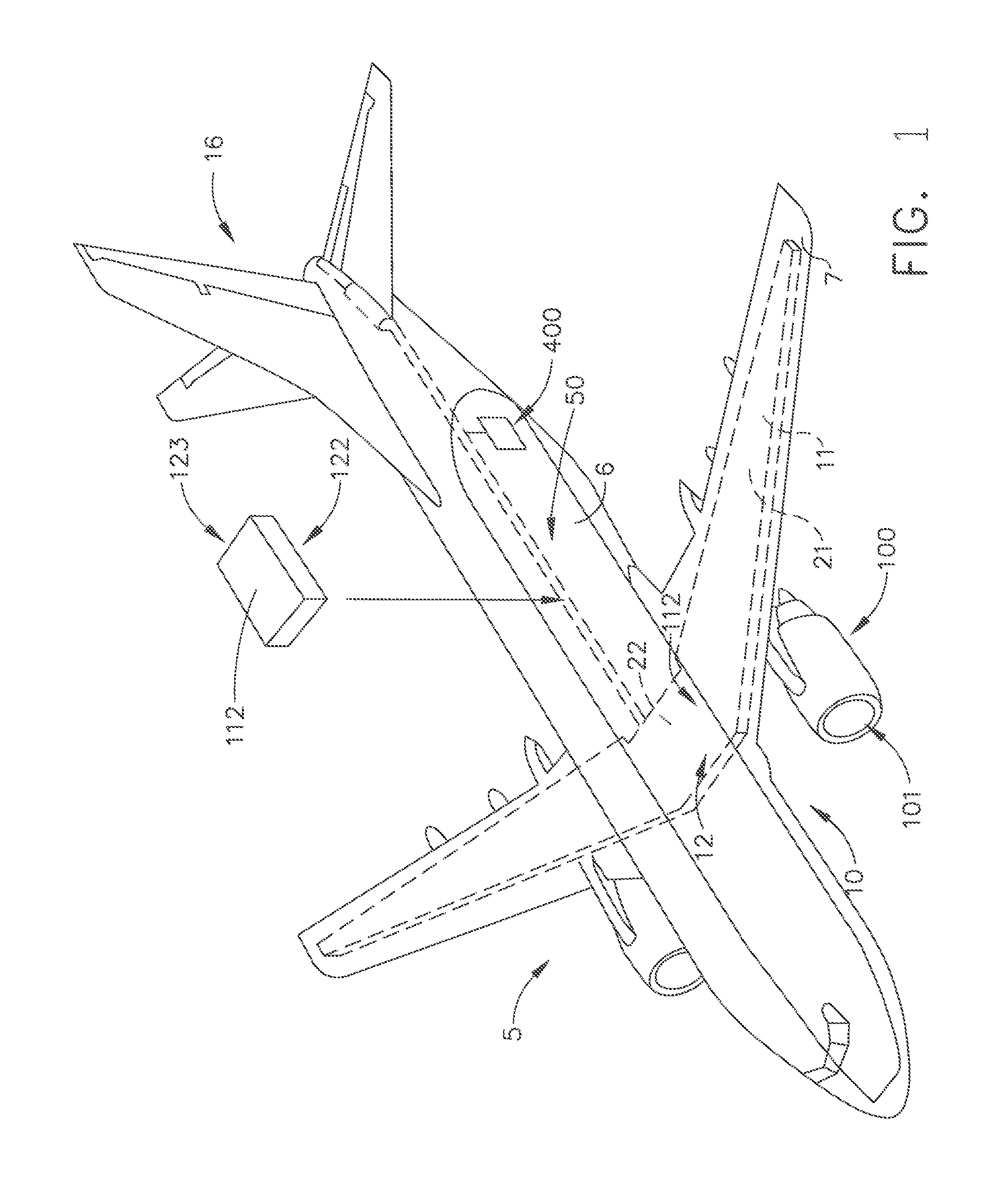
[0022]FIG. 1 shows an aircraft system 5 according to an exemplary embodiment of the present invention. The exemplary aircraft system 5 has a fuselage 6 and wings 7 attached to the fuselage. The aircraft system 5 has a propulsion system 100 that produces the propulsive thrust required to propel the aircraft system in flight. Although the propulsion system 100 is shown attached to the wing 7 in FIG. 1, in other embodiments it may be coupled to other parts of the aircraft system 5, such as, for example, the tail portion 16.

[0023]The exemplary aircraft system 5 has a fuel storage system 10 for storing one or more types of fuels that are used in the propulsion system 100. The exemplary aircraft system 5 shown in FIG. 1 uses two types of fuels, as explained further below herein. Accordingly, the exemplary aircraft system 5 comprises a first fuel tank 21 capable of sto...


PUM


Abstract

A dual fuel propulsion system comprising a gas turbine engine configured to generate a propulsive thrust using a cryogenic liquid fuel.

Description

CROSS-REFERENCE TO RELATED APPLICATION[0001]This is a national stage application under 35 U.S.C. §371(c), PCT application number PCT / US11 / 54396 filed on Sep. 30, 2011, which claims priority to U.S. Provisional Applications Ser. Nos. 61 / 388,350, 61 / 388,358, 61 / 388,396, and 61 / 388,408, filed Sep. 30, 2010, and Ser. No. 61 / 498,255, filed Jun. 17, 2011, the disclosures of which are hereby incorporated in their entirety by reference herein.BACKGROUND OF THE INVENTION[0002]The technology described herein relates generally to aircraft systems, and more specifically to aircraft systems using dual fuels in an aviation gas turbine engine and a method of operating same.[0003]Certain cryogenic fuels such as liquefied natural gas (LNG) may be cheaper than conventional jet fuels. Current approaches to cooling in conventional gas turbine applications use compressed air or conventional liquid fuel. Use of compressor air for cooling may lower efficiency of the engine system.[0004]Accordingly, it wou...

Claims


Application Information

Patent Timeline
Patent Type & Authority Applications(United States)
IPC IPC(8): F02K9/42
CPCF02C3/22F02C7/22F02C7/224F02C7/236F02C9/40F05D2260/85F05D2270/082Y02T50/672Y02T50/677F02K9/42F05D2270/08Y02T50/60
Inventor EPSTEIN, MICHAEL JAYMURROW, KURT DAVIDDINSMORE, NICHOLAS ROWEMARTIN, SAMUELVONDRELL, RANDYWEISGERBER, ROBERT HAROLDJOSHI, NARENDRA DIGAMBER
Owner GENERAL ELECTRIC CO
Why Eureka
Try Eureka