

Liquid fuel compositions for electrochemical fuel cells
a fuel cell and liquid fuel technology, applied in the direction of fuel cells, liquid carbonaceous fuels, electrochemical generators, etc., can solve the problems of inability to achieve simple methods, inability to prevent the widespread use of fuel cells in many applications, and inability to meet the requirements of hydrogen-powered fuel cells
Inactive Publication Date: 2004-07-06
MORE ENERGY
View PDF10 Cites 97 Cited by
- Summary
- Abstract
- Description
- Claims
- Application Information
AI Technical Summary
Benefits of technology
"The present invention relates to liquid fuel compositions for use in electrochemical fuel cells, methods of producing electricity with the fuel compositions, and fuel cells using the fuel compositions. The technical problem addressed by the invention is the need for a simple, efficient, and environmentally friendly fuel cell that can produce high power density with low fuel consumption and without the need for expensive and bulky high-pressure tanks for storage and transport of hydrogen. The invention proposes using direct-feed liquid fuel cells that overcome the limitations of current methods, such as fuel pre-processing and catalyst poisoning, and can utilize a wider range of fuel compositions. The invention also proposes using anolytes with low methanol content to improve fuel cell efficiency."
Problems solved by technology
Although fuel cells are increasingly gaining acceptance as electrical power sources, there are technical difficulties that prevent the widespread use of fuel cells in many applications.
Although fuel cells using hydrogen as a fuel are simple, clean and efficient the extreme flammability and the bulky high-pressure tanks necessary for storage and transport of hydrogen mean that hydrogen powered fuel cells are inappropriate for many applications.
These methods are not simple, requiring a fuel pre-processing stage and a complex fuel regulation system.
The number of available sites for further oxidation is reduced, reducing power output.
Unfortunately, acidic anolytes are most efficient at relatively high temperatures, temperatures at which the acidity can to passivate or destroy the anode.
Anolytes with a pH close to 7 are anode-friendly, but have an electrical conductivity that is too low for efficient electricity generation.
One disadvantage SPE membrane fuel cells have arises from the tendency of methanol to diffuse through the membrane.
As a result, much methanol is not utilized for generation of electricity but is lost through evaporation.
In addition if the methanol comes in contact with the cathode, a "short-circuit" occurs as the methanol is oxidized directly on the cathode, generating heat instead of electricity.
Further, depending upon the nature of the cathode catalyst and of the oxidant, catalyst poisoning or cathode sintering often occurs.
The low methanol content limits the efficiency of the fuel cell as the methanol diffusion rate limits electrical output.
Efficiency is also limited when measured in terms of electrical output as a function of volume of fuel consumed and raises issues of fuel transportation, dead weight and waste disposal.
Lastly, despite a high specific energy, methanol is rather unreactive.
As a result, the performance of direct-feed liquid methanol fuel cells is limited to about 5 mWcm.sup.-2.
The greatest drawbacks of hydrogen-containing inorganic compounds as fuel is the spontaneous decomposition of these compounds in acidic and neutral solutions, equation 6:
Is described above, hydrogen-containing inorganic compounds with a high reduction potential are good fuels for fuel cells but are plagued by over-reactivity.
Additionally, the presence of the auxiliary fuel increases the rate of catalytic oxidation of the primary fuel.
Engineering issues also dictate the exact composition of the fuel composition: for example, a fuel composition composed of methanol and NaBH.sub.4 could contain sodium methoxide as a stabilizing agent.
Method used
View moreImage
Smart ImageViewing Examples

Examples
example 2
The current at U=0.5 V was measured as a function of time in a fuel cell as in Example 1, wherein to the methanol / KOH solution 5 weight percent NaBH.sub.4 was added. A current of 240.+-.5 mA was measured over 90 minutes. The graph of the measured current as a function is time is presented in FIG. 3a.
While the invention has been described in respect to a limited number of embodiments, is will be appreciated that many variations, modifications and other applications of the invention may be made.
Login to View More PUM
| Property | Measurement | Unit |
|---|---|---|
| reduction potential | aaaaa | aaaaa |
| area | aaaaa | aaaaa |
| surface-active | aaaaa | aaaaa |
Abstract
A new fuel composition useful for catalytic fuel cells is made up of at least two components. The primary fuel component is a surface active compound, such as methanol, that is a source of and acts to prevent unwanted decomposition of the auxiliary fuel. The auxiliary fuel is a hydrogen-containing inorganic compound with a high reduction potential, such as NaBH4, which acts as a highly reactive source of energy and serves to catalyze the catalytic oxidation of the primary fuel.
Description
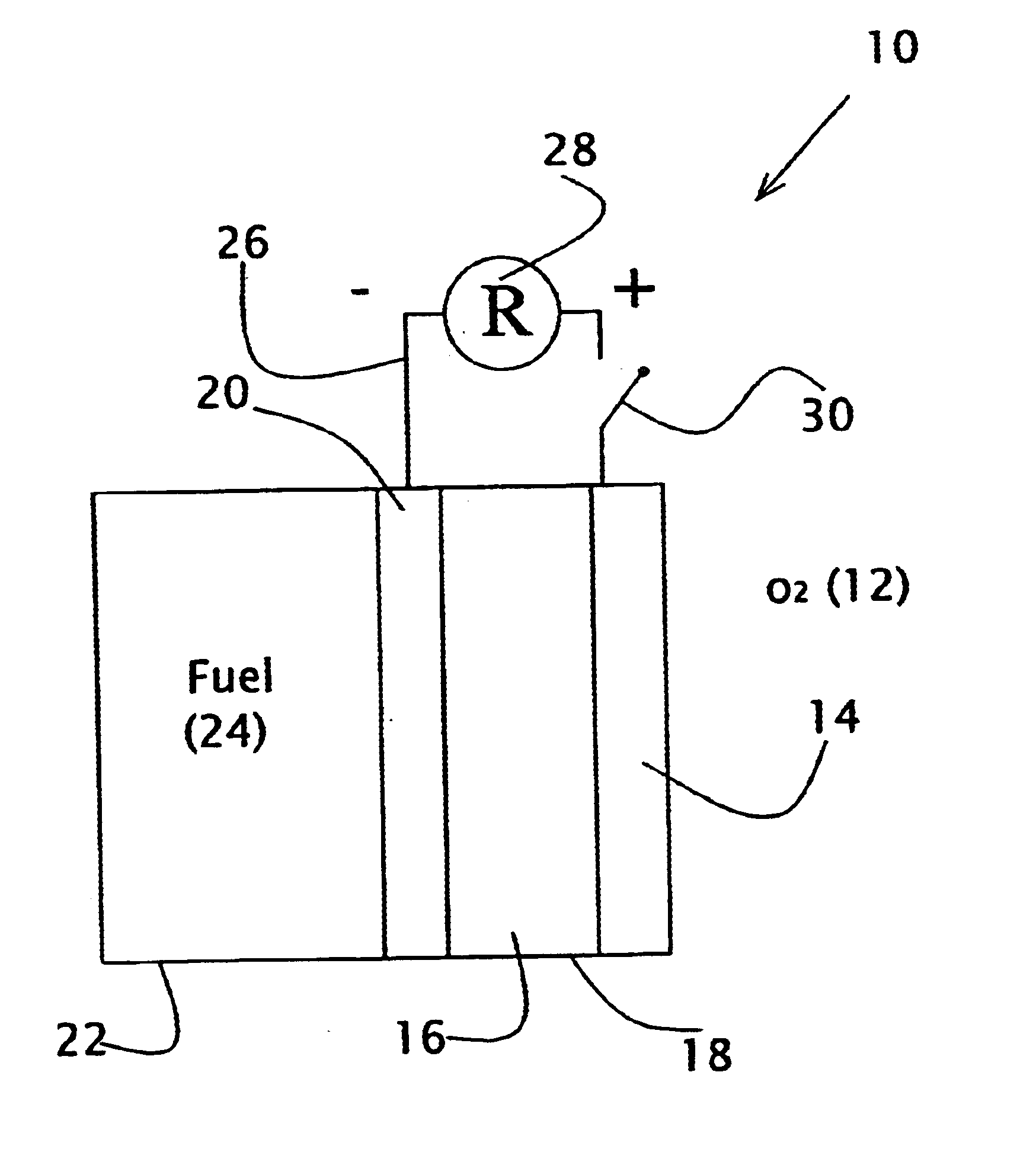
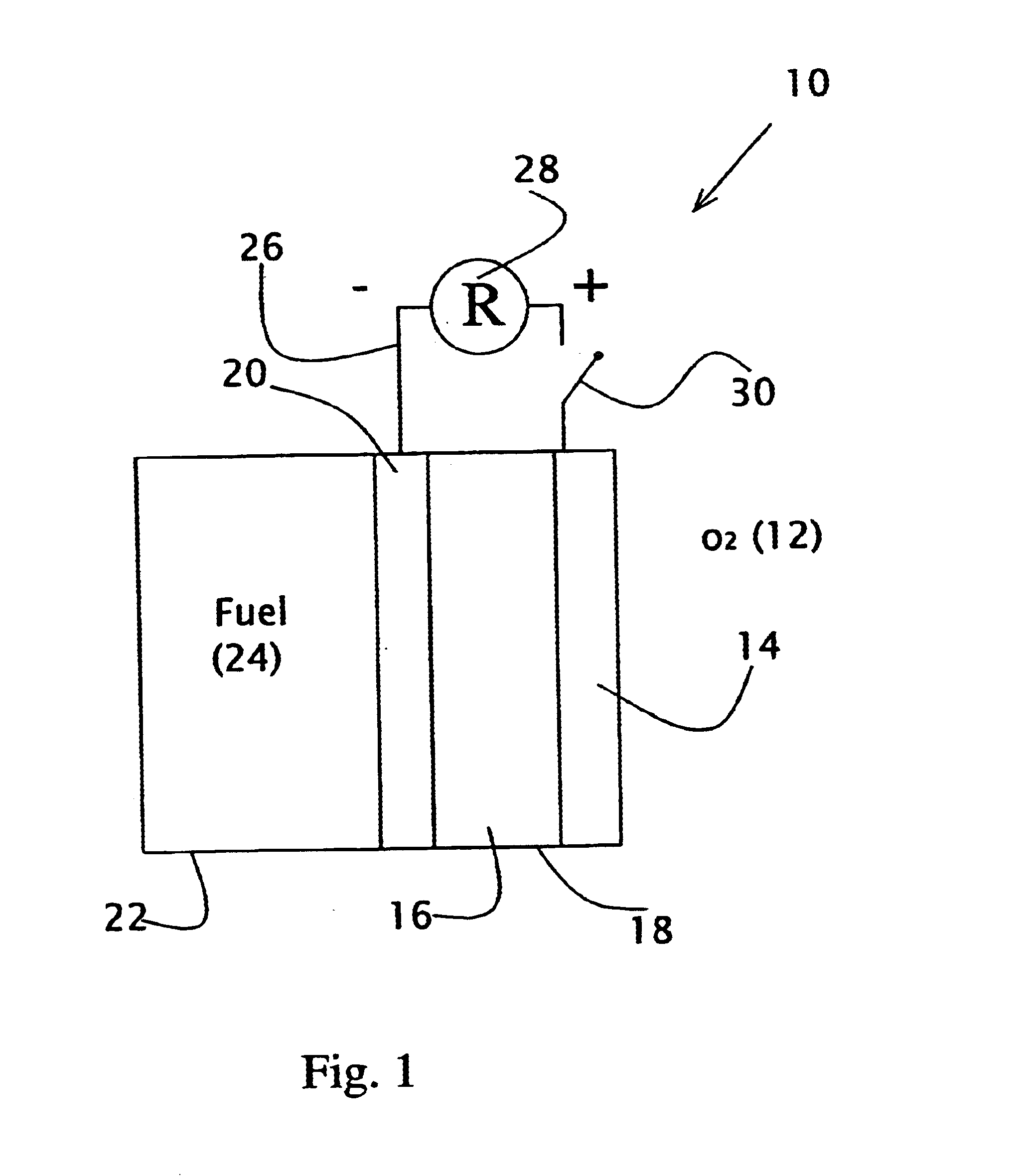
FIELD AND BACKGROUND OF THE INVENTIONThe present invention relates to liquid fuel compositions for use in electrochemical fuel cells, a method of producing electricity with the fuel compositions, and a fuel cell using the fuel compositions to generate electricity.A fuel cell is a device that converts the energy of a chemical reaction into electricity. Amongst the advantages that fuel cells have over other sources of electrical energy are high efficiency and environmental friendliness. Although fuel cells are increasingly gaining acceptance as electrical power sources, there are technical difficulties that prevent the widespread use of fuel cells in many applications.A fuel cell produces electricity by bringing a fuel and an oxidant in contact with a catalytic anode and a catalytic cathode, respectively. When in contact with the anode, the fuel is catalytically oxidized on the catalyst, producing electrons and protons. The electrons travel from the anode to the cathode through an ele...
Claims
Login to View More Application Information
Patent Timeline
 Patent Type & AuthorityPatents(United States)
IPC IPC(8): C10L1/02C10L1/00C10L1/12C10L1/10
CPCC10L1/02C10L1/1216C10L1/1266
InventorFINKELSHTAIN, GENNADYKATSMAN, YURIFILANOVSKY, BORIS
OwnerMORE ENERGY