On-board fuel vapor collection, condensation, storage and distribution system for a vehicle

a technology of fuel vapor collection and condensation, which is applied in the direction of machines/engines, combustion air/fuel air treatment, electric control, etc., can solve the problems of excessive evaporate emissions, prohibitively large charcoal canisters, and inability of vehicle fuel systems to contain volatile fuel vapors

Inactive Publication Date: 2002-12-17
SOUTHWEST RES INST
View PDF8 Cites 96 Cited by
  • Summary
  • Abstract
  • Description
  • Claims
  • Application Information

AI Technical Summary

Problems solved by technology

Currently, vehicle fuel systems are unable to contain volatile fuel vapors that escape during their refueling process.
During hot weather and / or during long engine idle periods, such as in heavy traffic, the charcoal canisters can become saturated and vent fuel vapors to the atmosphere, resulting in excessive evaporate emissions.
To contain all of the vapors generated by the worst case scenario, a charcoal canister would have to be prohibitively large.
None of the above-described systems are appropriate for on-board vapor recovery systems which are expected to be needed to meet ever-increasingly stringent vehicle evaporate emissions standards.

Method used


Image

  • On-board fuel vapor collection, condensation, storage and distribution system for a vehicle
  • On-board fuel vapor collection, condensation, storage and distribution system for a vehicle

Examples


Embodiment Construction

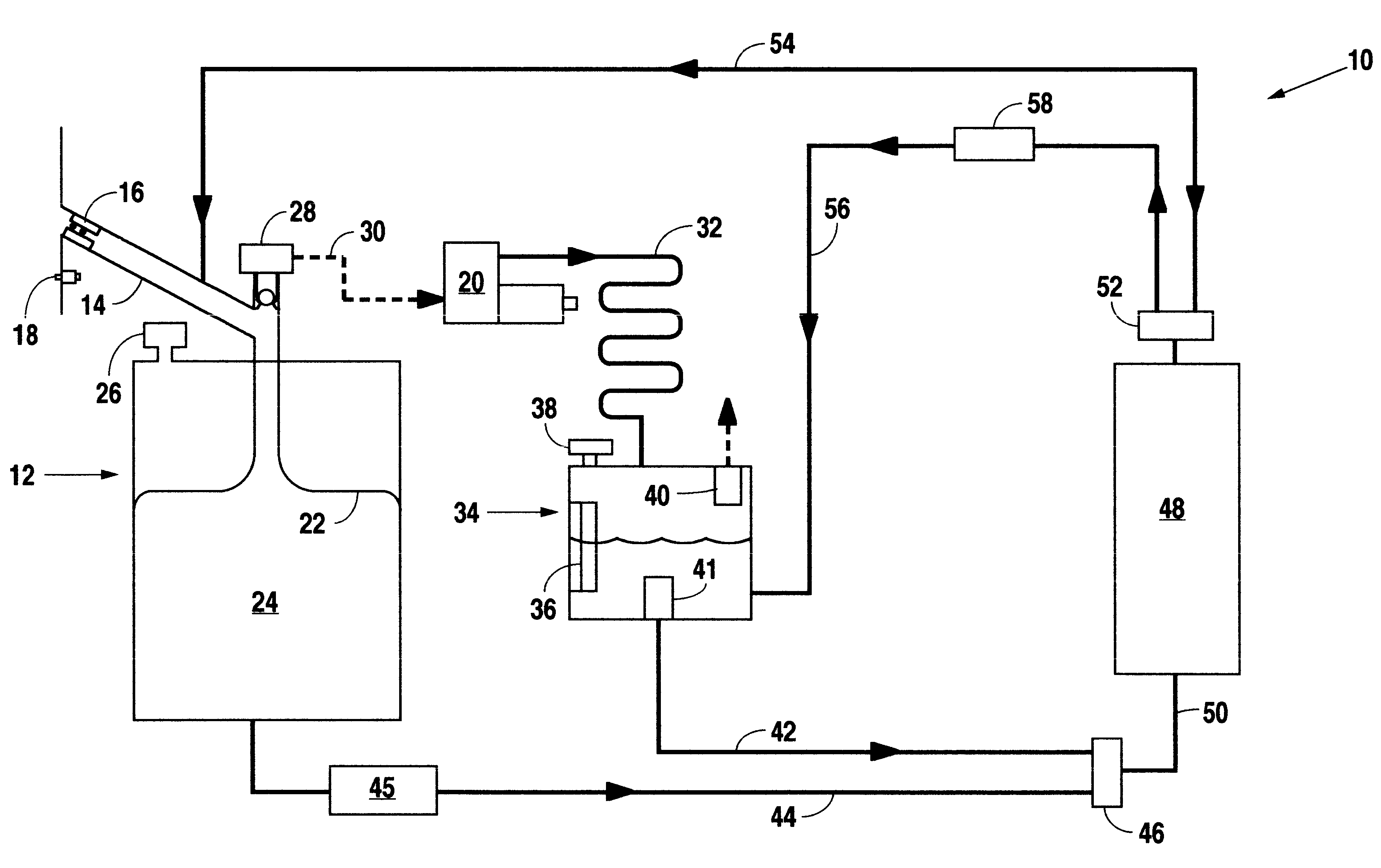
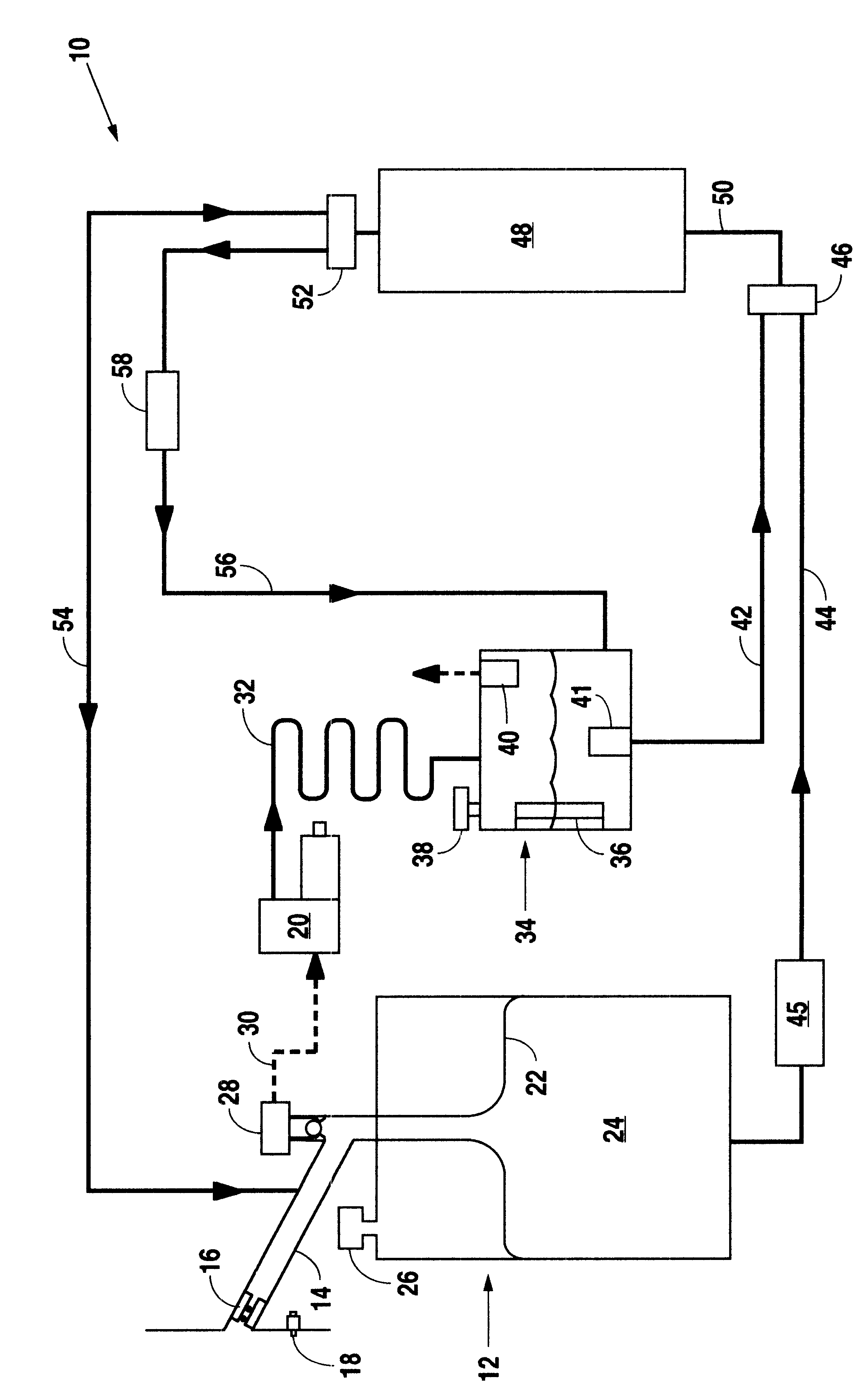
In the present embodiment of the present invention, as shown in the accompanying drawing, an on-board fuel vapor collection, condensation, storage and distribution system 10, mounted on a vehicle, includes a fuel tank 12 that has a filler tube 14 providing for the selective addition of fuel to the tank 12. A fuel nozzle seal 16, for example similar to the nozzle described in the above-referenced U.S. Pat. No. 3,752,355, is provided in the entry neck of the filler tube 14 to provide a seal around a fuel nozzle when fuel is being added to the tank 12. Desirably, a fuel door switch 18 is arranged to provide a signal for activation of a compressor 20 when the fuel door is opened to deliver fuel to the tank 12.

The fuel tank 12 has a flexible bladder 22 disposed within the tank that is arranged to receive fuel delivered through the filler tube 14 and provide a volumetrically variable fuel chamber 24 within the tank 12 for storing the liquid fuel. A pressure regulator 26 provides pressure ...


PUM


Abstract

An on-board fuel vapor recovery system draws vapors from a fuel tank, compresses the vapors, and then cools the compressed vapors to form a condensate liquid fuel which is stored in an auxiliary condensate tank for introduction to an engine for enhanced cold start operation.

Description

1. Technical FieldThis invention relates generally to a system carried on a vehicle for collecting, condensing, storing, and distributing volatile fuel vapors, and more particularly such a system that condenses volatile fuel vapors by compression and cooling to form a liquid fuel stored in a condensate tank for use as a desirable fuel for cold start engine operation.2. Background ArtCurrently, vehicle fuel systems are unable to contain volatile fuel vapors that escape during their refueling process. The vapor space in the tank is displaced by the entering liquid fuel, and fuel vapors are purged out of the fuel pipe to the atmosphere. In addition to vapors lost during refueling, changing ambient conditions allow liquid fuel to vaporize within the tank. These vapors are generally stored in charcoal canisters on the vehicle and are later drawn into the engine intake and consumed during cruise conditions. During hot weather and / or during long engine idle periods, such as in heavy traffi...

Claims


Application Information

Patent Timeline
Patent Type & Authority Patents(United States)
IPC IPC(8): F02M37/20
CPCF02M37/20
Inventor CAPSHAW, WILLIAM K.HEDRICK, JOHN C.NAEGELI, DAVID W.ROSS, MICHAEL G.
Owner SOUTHWEST RES INST
Why Eureka
Try Eureka