Piecemeal Turbojet

a technology of piecemeal and turbojet, which is applied in the direction of jet propulsion plants, rocket engine plants, machines/engines, etc., to achieve the effect of saving a lot of development costs and tim

Inactive Publication Date: 2013-07-25
KOSHELEFF PATRICK A
View PDF1 Cites 15 Cited by
  • Summary
  • Abstract
  • Description
  • Claims
  • Application Information

AI Technical Summary

Benefits of technology

[0002]A turbojet including major parts from several existing turbofan engines. The object is to save much of the development cost and time of a new turbojet for a special purpose. Turbofan engines come in two kinds. The high-bypass kind is used in large subsonic airliners which can carry 300 or more passengers acros...

Problems solved by technology

But there...

Method used


Image

  • Piecemeal Turbojet
  • Piecemeal Turbojet
  • Piecemeal Turbojet

Examples


embodiment

An Improved Embodiment

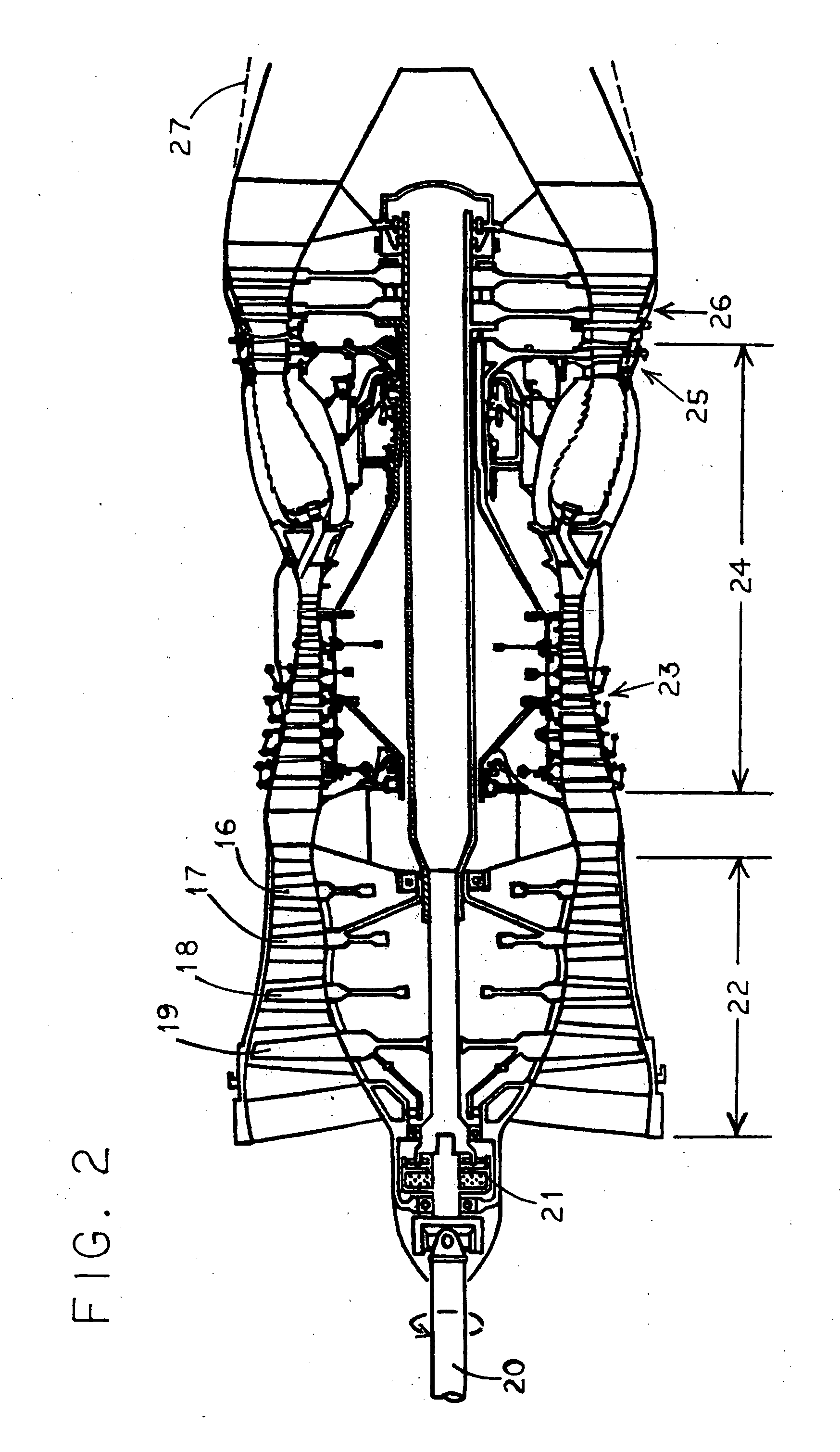
[0039]The main change in FIG. 2 is that HP section 24 is much shorter. HP compressor 23 has 6 stages, not 11, and HP turbine 25 is single-stage, not 2-stage. In other words, about half of JT9D's HP core has been removed—The inner half. This is possible because the two stages of JT9D's HP turbine approximately divided the work of turning the HP compressor. That usually maximizes the efficiency.

[0040]The remote fan (not shown) which will be driven by driveshaft 20 is seen as FIG. 10 of U.S. Pat. No. 3,161,019. It's expected that it will double the subsonic air mass flow, thereby increasing the propulsive efficiency. Unlike the remote fan in U.S. Pat. No. 3,161,019, ours would only be two stages, probably the same size as stages 19 and 18, and delivering the same pressure ratio of 2.2. In other words, it could be just the F101 fan again. Again unlike U.S. Pat. No. 3,161,019, our remote fan would not discharge into the engine's exhaust nozzle, but under the engine ...


PUM


Abstract

A two-spool turbojet built up of major bladed components first developped for unrelated turbofan engine types. The high pressure (“HP”) spool comes from a turbofan which powered a large airliner carrying 300 or more passengers across a continent or an ocean. The low pressure (“LP”) compressor is the fan from a military aircraft's engine or a smaller airliner turbofan, or both. The object is that all the LP compressor output goes into the HP compressor, making a turbojet from existing turbofan components. This saves development costs, and creates an engine for propelling a large aircraft at supersonic speeds more efficiently than by an afterburning turbofan. In the preferred embodiment, the number of stages in the HP spool is halved, saving weight for the addition of a remote fan (known elsewhere) which doubles the air mass flow. That increases propulsive efficiency during subsonic cruise.

Description

BACKGROUND OF THE INVENTION[0001]A turbojet of conventional design but using major parts from existing engines. The high pressure (“HP”) spool uses blading from a large turbofan and the low pressure (“LP”) spool uses blading from a small turbofan. Prior examples were not encountered in the art. The advantage expected here is that these major components are already developped, for reduced cost. Known turbojet low propulsive efficiency is an issue. Turning a remote fan by a driveshaft from the front of the turbojet is deemed useful. U.S. Pat. No. 3,161,019 shows such an arrangement in its FIG. 10.SUMMARY OF THE INVENTION[0002]A turbojet including major parts from several existing turbofan engines. The object is to save much of the development cost and time of a new turbojet for a special purpose. Turbofan engines come in two kinds. The high-bypass kind is used in large subsonic airliners which can carry 300 or more passengers across a continent or an ocean. The second kind is much sma...

Claims


Application Information

Patent Timeline
IPC IPC(8): F02K3/00
CPCF05D2230/52F02K3/06F02K3/00F05D2230/51F02C3/04
Inventor KOSHELEFF, PATRICK A.
Owner KOSHELEFF PATRICK A
Why Eureka
Try Eureka