Vibration Damping Device

a vibration damping device and vibration damping technology, which is applied in the direction of fluid couplings, rotary clutches, gearing, etc., can solve the problems of generating noise, reducing the capacity of the chamber, and reducing the durability of the rotary member, so as to prevent or suppress the noise of collisions, the structure of the vibration damping device of the present invention is simple and the vibration damping capacity is excellen

Active Publication Date: 2013-07-25
TOYOTA JIDOSHA KK
View PDF6 Cites 12 Cited by
  • Summary
  • Abstract
  • Description
  • Claims
  • Application Information

AI Technical Summary

Benefits of technology

[0012]According to the present invention, in case a speed inputted to the hydraulic transmission is comparatively low, or in case a torque inputted to the hydraulic transmission is comparatively large, the lockup clutch is disengaged for the purpose of damping vibrations by a buffering action of the fluid. In this situation, the movable member is actuated by the fluid pressure for disengaging the lockup clutch, and the rolling member is locked by the movable member thus actuated. As a result, the rolling member locked in the holding chamber is restricted to move freely. Therefore, the rolling member will not collide against the inner face of the holding chamber so that the noise resulting from such collision can be prevented or suppressed. For this purpose, the movable member is frictionally contacted with the rolling member, therefore, the rolling member can be locked certainly.
[0013]To the contrary, the lockup clutch is engaged in case the speed inputted to the hydraulic transmission is increased, or in case the torque inputted to the hydraulic transmission is reduced. In this case, the movable member is actuated by the fluid pressure for engaging the lockup clutch in the direction to unlock the rolling member. As a result, the rolling member is allowed to move freely in the holding chamber. Therefore, even if torsional vibrations are generated on the driven side impeller or the member integrated therewith, the rolling member is moved relatively in the holding chamber and the torsional vibrations are absorbed and damped by such relative displacement of the rolling member. That is, in case the rotational speed is increased, the vibration damping device functions to damp the vibrations. Thus, according to the present invention, the holding chamber is formed partially by the movable member, and the movable member is actuated to lock and unlock the rolling member by the fluid pressure for engaging and disengaging the lockup clutch. Therefore, the vibration damping device of the present invention can be formed by merely modifying the structure of the holding chamber without using additional members. Thus, the structure of the vibration damping device of the present invention is simple, but the vibration damping capacity thereof is excellent.

Problems solved by technology

As a result, noise is generated and durability of the rotary member is degraded.
However, according to the teachings of Japanese Patent Laid-Open No. 7-280037, a volume of the rolling member is rather small in comparison with a capacity of the chamber.
In addition, it is difficult to situate the rolling member certainly at the outer circumferential side in the chamber.
For these reasons, vibration damping capacity of the vibration absorber taught by Japanese Patent Laid-Open No. 7-280037 is insufficient.
Moreover, it is rather difficult to set elasticity of the elastomer to a value possible to hold the rolling member away from the inner face of the storing chamber in a low-speed region, and also possible to damp the vibrations of target frequency.
Further, the elastomer will be deteriorated with age, and if the elastomer is deteriorated, noise would be generated and the vibration damping capacity would be changed.

Method used


Image

  • Vibration Damping Device
  • Vibration Damping Device
  • Vibration Damping Device

Examples


Embodiment Construction

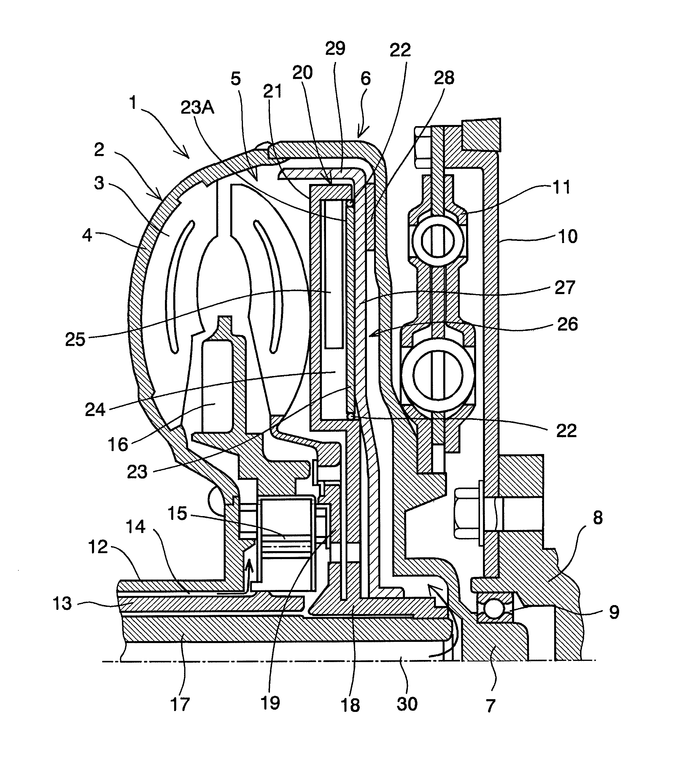
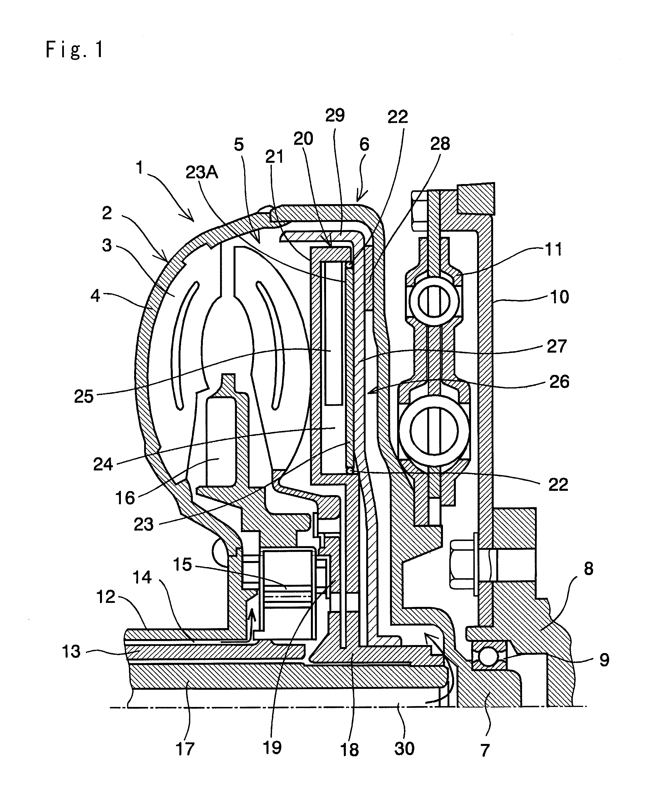
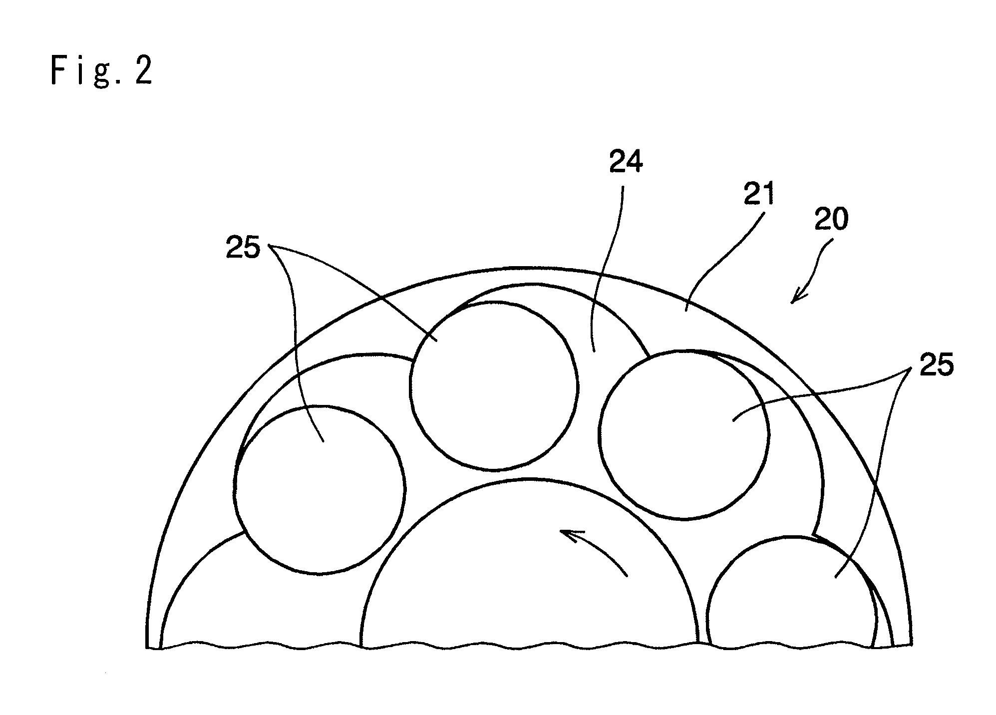
[0018]Next, this invention will be explained in more detail. The vibration damping device according to the present invention is a pendulum type vibration damping device. Specifically, according to the vibration damping device of the present invention, rolling members are held in a rotary member rotated by a torque, and each of the rolling members functioning as a weight is allowed to move relatively and freely in the rotary member. According to the present invention, the vibration damping device thus structured is arranged in a hydraulic transmission having a lock-up clutch, and the rolling members are locked and unlocked utilizing pressure for engaging and disengaging the lock-up clutch.

[0019]FIG. 1 is a view showing an example in which the vibration damping device is arranged in a torque converter 1 as a hydraulic transmission capable of amplifying torque. The torque converter 1 shown therein is structured as a conventional torque converter widely used in vehicles. Specifically, a...


PUM


Abstract

To provide a simply-structured vibration damping device having excellent vibration damping capacity.
A vibration damping device is configured to damp torsional vibrations of a rotary member of a hydraulic transmission 1, in which the rotary member is rotated integrally with a drive side impeller 2 or with a driven side impeller 5, and in which the drive side impeller 2 and the driven side impeller 5 are connected with a lockup clutch 26 actuated by fluid pressure. The vibration damping device comprises: a holding chamber 24 rotated integrally with the driven side impeller 5; a rolling member 25 held in the holding chamber 24, which is rotated in a rotational direction of the driven side impeller 5 but allowed to rotate relatively with the driven side impeller 5; and a movable member 23 configured to lock the rolling member 25 in the holding chamber 24 when actuated by the fluid pressure for disengaging the lockup clutch 26, and to unlock the rolling member 25 in the holding chamber 24 when actuated by the fluid pressure for engaging the lockup clutch 26.

Description

TECHNICAL FIELD[0001]This invention relates to a vibration damping device for damping torsional vibrations, and especially to a vibration damping device comprising a rotary member rotated by torque and a rolling member held in the rotary member while being allowed to rotate relatively with the rotary member.BACKGROUND ART[0002]A rotary member such as a drive shaft, gear and so on used to transmit a torque from a prime mover to a desired portion or a member is vibrated inevitably by a fluctuation of the torque or load, or by a friction. A frequency of the vibration is varied according to rotational speed, and high order vibrations such as secondary vibrations are also generated. Therefore, amplitude of vibrations is widened by resonance. As a result, noise is generated and durability of the rotary member is degraded. Examples of a device or mechanism for suppressing such vibrations of equipment for transmitting power by rotation is disclosed in Japanese Patent Laid-Open No. 7-280037 ...

Claims


Application Information

Patent Timeline
Patent Type & Authority Applications(United States)
IPC IPC(8): F16F15/14F16H45/02
CPCF16F15/145F16H2045/0205F16F15/14F16H2045/0226F16H45/02Y10T74/2128F16H2045/0252F16H2045/0294
Inventor MIYAHARA, YUAMANO, HIROYUKISUENAGA, SHINICHIROAIJIMA, SHINGO
Owner TOYOTA JIDOSHA KK
Why Eureka
Try Eureka