Spot Welding Clamp and A Spot Welding Process

Inactive Publication Date: 2013-07-25
DONGGUAN NVT TECH
View PDF2 Cites 5 Cited by
  • Summary
  • Abstract
  • Description
  • Claims
  • Application Information

AI Technical Summary

Benefits of technology

[0007]One of the aims of the invention is to provide a spot welding clamp which can avoid rosin joint

Problems solved by technology

However, the projection point of the copper foot of the fuse is arranged upwards and the Ni/Al cladding strip is provided with a double-layer structure, which leads to relatively large difficulty in spot welding and easily causes rosin joint or false welding, or even insufficient tension, thus producing a large amount of defective products and affecting product quality.
Moreover, professionals need to find out rosin joint or false welding for repair welding, which is time and labor-consuming and

Method used


Image

  • Spot Welding Clamp and A Spot Welding Process
  • Spot Welding Clamp and A Spot Welding Process

Examples


Embodiment Construction

[0024]The following further gives detailed description of the invention through embodiment and the drawings attached to the description, but the embodiment of the invention is not limited to the embodiment herein.

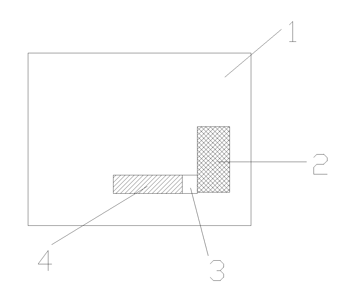
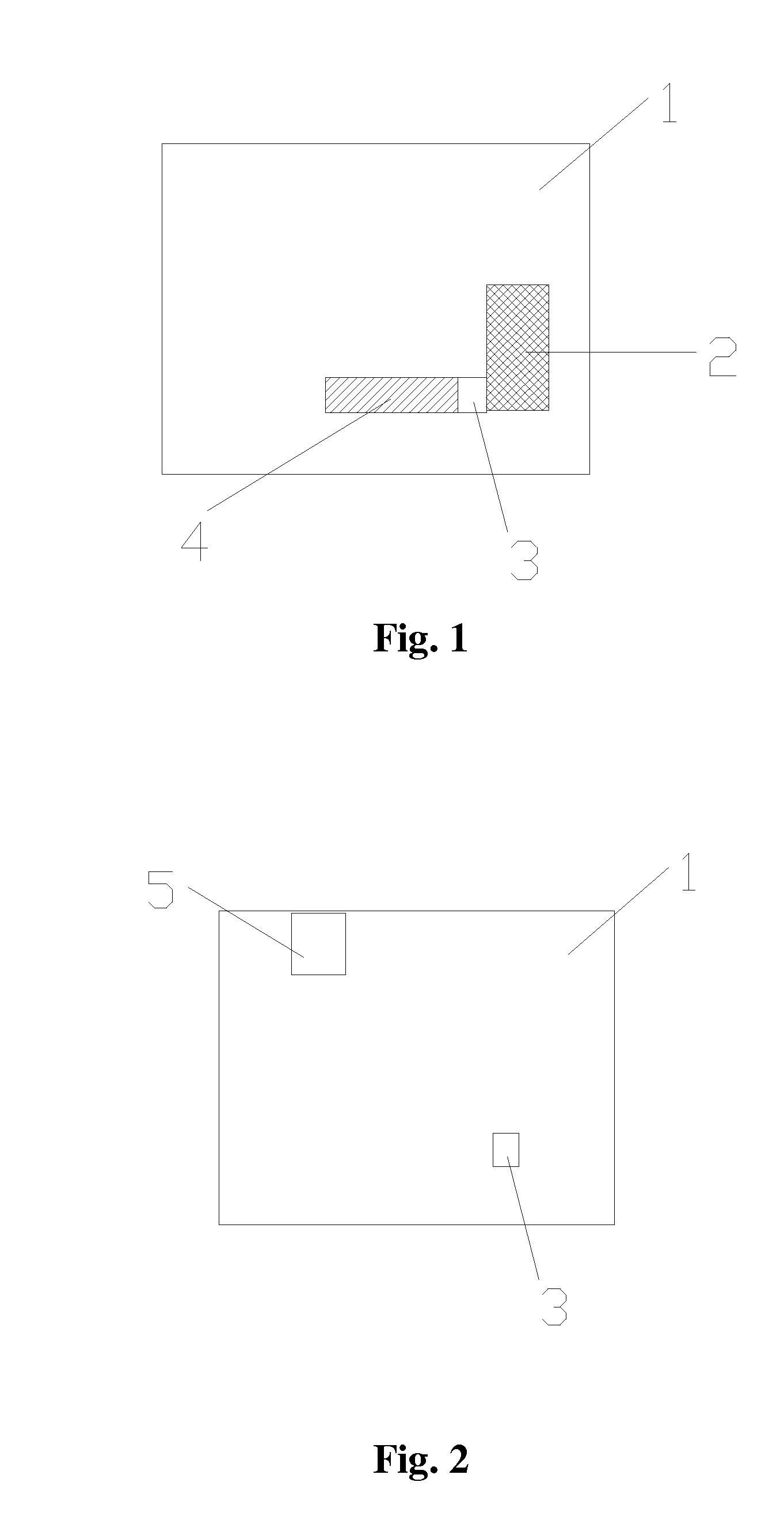
[0025]As shown in FIG. 1 and FIG. 2, the invention provides a spot welding clamp which comprises a clamp body 1, an electric core holding area 2 and a fuse holding area 3, wherein the electric core holding area 2 and the fuse holding area 3 are arranged on the clamp body 1. A clearance 4 is arranged between the electric core holding area 2 and the fuse holding area 3. The electric core holding area 2 and the fuse holding area 3 are arranged vertically. The electric core holding area 2 has a groove structure. The fuse holding area 3 has a groove structure. A tab made of a Ni / Al cladding strip is arranged on an electric core.

[0026]As shown in FIG. 2, the adjuster 5 used for adjusting the welding pin is arranged on the clamp body 1.

[0027]When the clamp is used for carrying out...


PUM

PropertyMeasurementUnit
Areaaaaaaaaaaa
Heightaaaaaaaaaa

Abstract

The invention belongs to the technical field of welding, and in particular relates to a spot welding clamp which avoids rosin joint, false welding and fire blasting and is used in spot welding process with high efficiency. The spot welding clamp comprises a clamp body, an electric core holding area and a fuse holding area, wherein the electric core holding area and the fuse holding area are arranged on the clamp body. A clearance is arranged between the electric core holding area and the fuse holding area. Compared with the prior art, the spot welding clamp can well position a fuse and a metal strip and adjust the height of a welding pin, thus improving spot welding quality, lowering welding defect rate, improving productivity and reducing cost. In addition, the invention also discloses a spot welding process using the spot welding clamp.

Description

TECHNICAL FIELD[0001]The invention belongs to the technical field of welding, and in particular relates to a spot welding clamp which avoids rosin joint, false welding and fire blasting and is used for efficient spot welding process.BACKGROUND OF THE INVENTION[0002]With the continuous development of electronic equipment, the battery, as the power supply of electronic equipment, also enjoys a rapid development and is designed to be thinner and lighter following the miniaturization of the electronic equipment.[0003]A battery commonly comprises an electric core, a protection board arranged at the front end of the electric core and other relevant structural components such as a front cover, a rear cover and a shell. The fuse is generally arranged on the protection board. When the temperature of the battery reaches to certain extent, the fuse can cut off the circuit to avoid the explosion of the battery. The connection between the electric core and the fuse is realized by the spot weldin...

Claims


Application Information

Patent Timeline
IPC IPC(8): B23K11/11
CPCB23K11/314
Inventor WEI, JOHNNYZHOU, HELLEN
Owner DONGGUAN NVT TECH
Why Eureka
Try Eureka