
Rear-Mounted Vehicular Wind Power Generator System

Inactive Publication Date: 2013-07-25
CHUNG HSIEN CHEN
View PDF1 Cites 1 Cited by
  • Summary
  • Abstract
  • Description
  • Claims
  • Application Information

AI Technical Summary

Benefits of technology

The present invention proposes a rear-mounted vehicular wind power generator system to solve issues with conventional wind power generators. The system is mounted in the rear of a vehicle and comprises a power generator, a blade wheel, a power generator shaft, an air guiding hood, wires, and fixed terminals. When the vehicle is running, air flows through the air guiding hood and drives the blade wheel to rotate. The power generator shaft is fixed to the blade wheel and transmits dynamic energy to the power generator, resulting in the generation of electric energy. The electric energy is stored in a battery for various applications. The technical effect of the invention is that the wind power generator system is mounted in the rear of a vehicle, balancing the vehicle's load and ensuring safe driving.

Problems solved by technology

If the wind power generator is mounted in the front of a vehicle and has large blades, the blades should hinder vision of the driver.
Therefore, the size of the front-mounted vehicular wind power generator must be limited lest it hinder the vision of the driver.
Thus is also limited the capacity of the front-mounted vehicular wind power generator.
If the wind power generator is mounted in the top of a vehicle, the balance of the vehicle would be affected when the vehicle is running at high speed.
Therefore, it is inappropriate to mount a wind power generator in the front or top of a vehicle.

Method used


Image

  • Rear-Mounted Vehicular Wind Power Generator System
  • Rear-Mounted Vehicular Wind Power Generator System
  • Rear-Mounted Vehicular Wind Power Generator System

Examples


Embodiment Construction

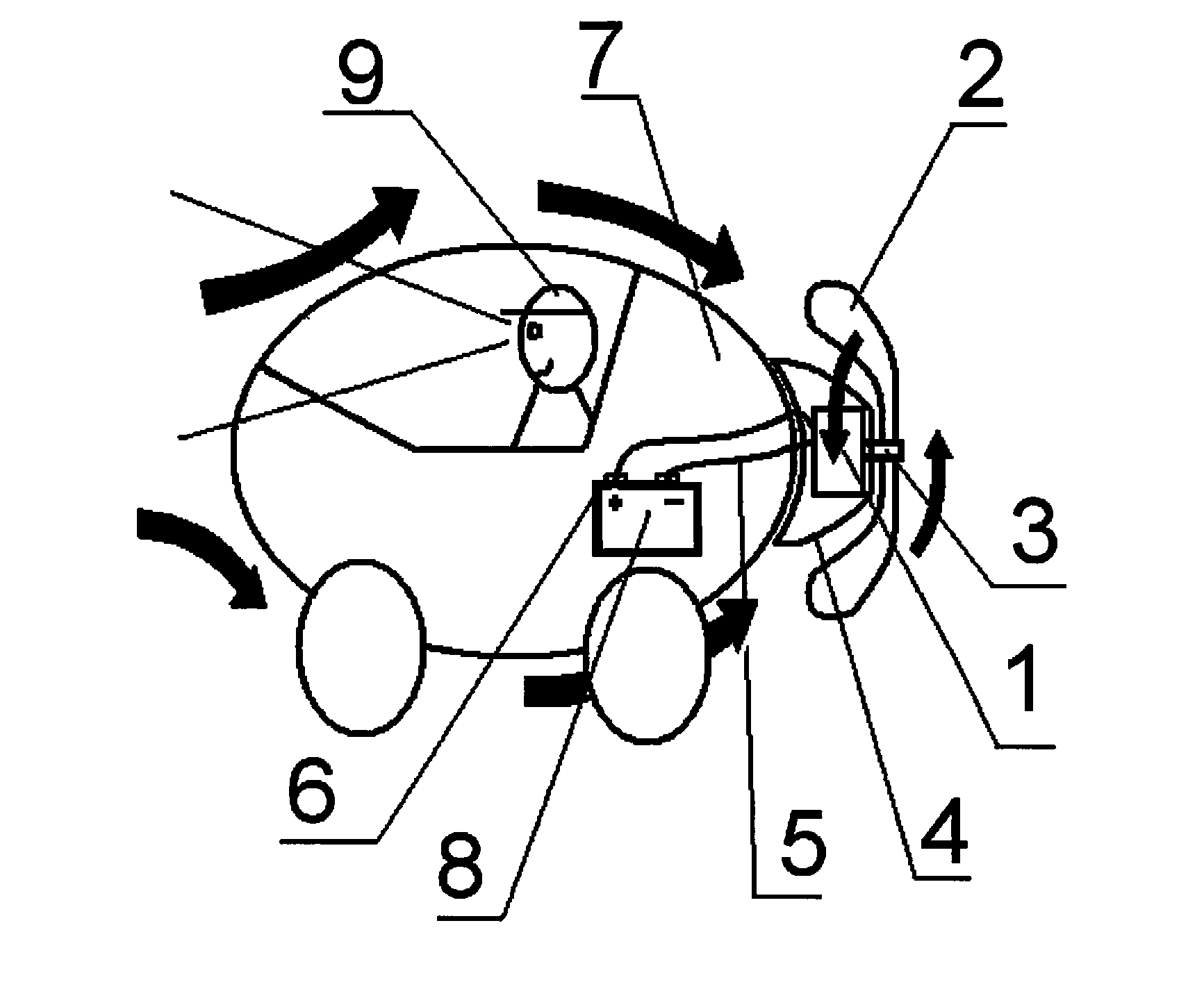
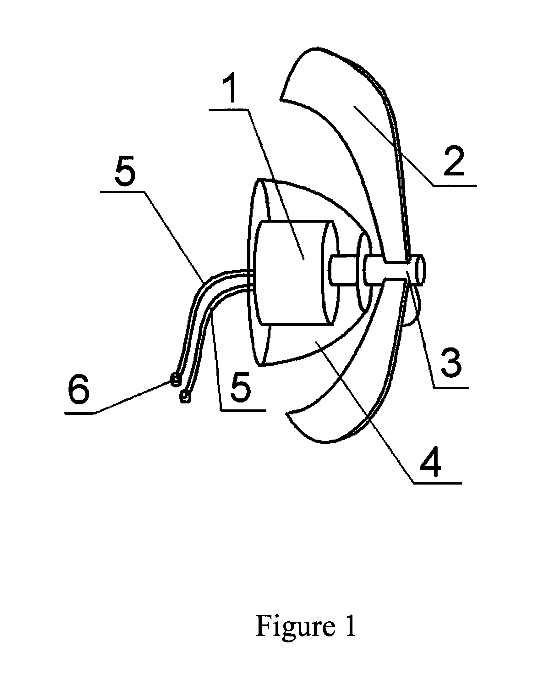
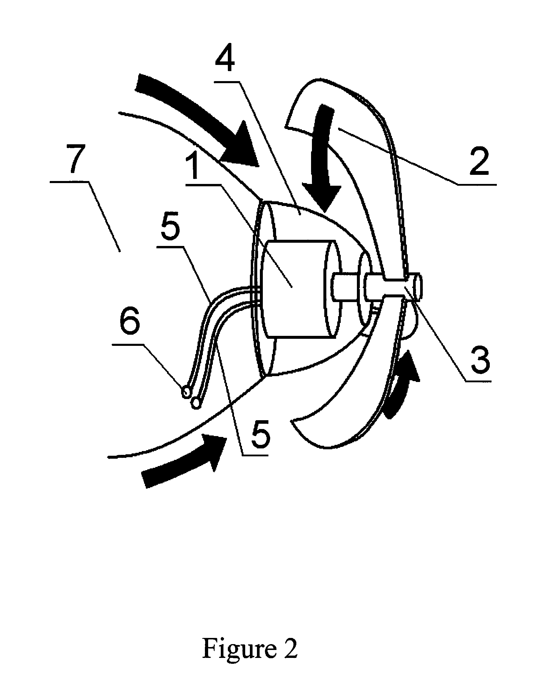
[0016]Refer to FIG. 1, FIG. 2 and FIG. 3. The present invention discloses a rear-mounted wind power generator system, which comprises a power generator 1, a blade wheel 2, a power generator shaft 3, an air guiding hood 4, wires 5 and fixed terminals 6.

[0017]Below is described in detail the components of the rear-mounted vehicular wind power generator system of the present invention and the connection relationship thereof. The vehicular wind power generator system of the present invention is mounted in the rear of a vehicle 7. The wind power generator system has a power generator 1, and the power generator 1 has a power generator shaft 3. A blade wheel 2 is fixed to the power generator shaft 3 and rotated by wind. The power generator shaft 3 is rotated by the blade wheel 2 to drive the power generator 1 to generate electric energy. An air guiding hood 4 has a smooth and streamline surface and is arranged outside the power generator 1 for guiding air stream. The power generator 1 is c...


PUM


Abstract

A rear-mounted vehicular power generator system comprises a power generator, a blade wheel, a power generator shaft, an air guiding hood, wires, and fixed terminals. The vehicular wind power generator system is mounted in the rear of a vehicle. When the vehicle is running, air flows through the air guiding hood and drives the blade wheel to rotate. The power generator shaft, which is fixed to the blade wheel, rotates together with the blade wheel and drives the power generator to generate electric energy. The electric energy is stored in a battery for various applications. The present invention is characterized in that the vehicular wind power generator system is mounted in the rear of a vehicle, neither hindering vision of the driver nor impairing balance of the vehicle running at high speed.

Description

BACKGROUND OF THE INVENTION[0001]1. Field of the Invention[0002]The present invention relates to a wind power generator integrated with a vehicle, particularly to a power generator mounted in the rear of a vehicle and driven to generate power by the wind created by the running vehicle.[0003]2. Description of the Related Art[0004]At present, the vehicular wind power generator is normally mounted in the front or top of a vehicle. If the wind power generator is mounted in the front of a vehicle and has large blades, the blades should hinder vision of the driver. Therefore, the size of the front-mounted vehicular wind power generator must be limited lest it hinder the vision of the driver. Thus is also limited the capacity of the front-mounted vehicular wind power generator. If the wind power generator is mounted in the top of a vehicle, the balance of the vehicle would be affected when the vehicle is running at high speed.[0005]Therefore, it is inappropriate to mount a wind power gener...

Claims


Application Information

Patent Timeline
IPC IPC(8): F03D9/02
CPCF03D1/04Y02E10/728F05B2240/941F03D11/04Y02E10/72Y02E70/30B60K16/00F03D9/32F03D9/25F03D9/11F03D13/20
Inventor CHEN, CHUNG-HSIEN
Owner CHUNG HSIEN CHEN
Learn More