Motor and rotor thereof

a rotor and motor technology, applied in the direction of dynamo-electric machines, magnetic circuit rotating parts, magnetic circuit shape/form/construction, etc., can solve the problems of deformation or damage of the core of the rotor, partial leakage of magnetic flux toward the rotating shaft, disadvantages in material cost and motor miniaturization, etc., to achieve enhanced durability and improve structure

Active Publication Date: 2013-07-25
SAMSUNG ELECTRONICS CO LTD
View PDF7 Cites 31 Cited by
  • Summary
  • Abstract
  • Description
  • Claims
  • Application Information

AI Technical Summary

Benefits of technology

[0011]Therefore, it is an aspect of the present invention to provide a rotor having an improved structure capable of achieving an enhanced durability, and a motor including the same.

Problems solved by technology

In such a spoke type permanent magnet motor, the cores of the rotor may be deformed or damaged due to centrifugal force generated during high-speed rotation of the rotor because the body of the rotor is weak in terms of structure.
Furthermore, in the spoke type permanent magnet motor, magnetic flux may partially leak toward the rotating shaft through the cylindrical supports of the rotor body.
In this case, accordingly, there may be disadvantages in terms of material costs and motor miniaturization

Method used


Image

  • Motor and rotor thereof
  • Motor and rotor thereof
  • Motor and rotor thereof

Examples


Embodiment Construction

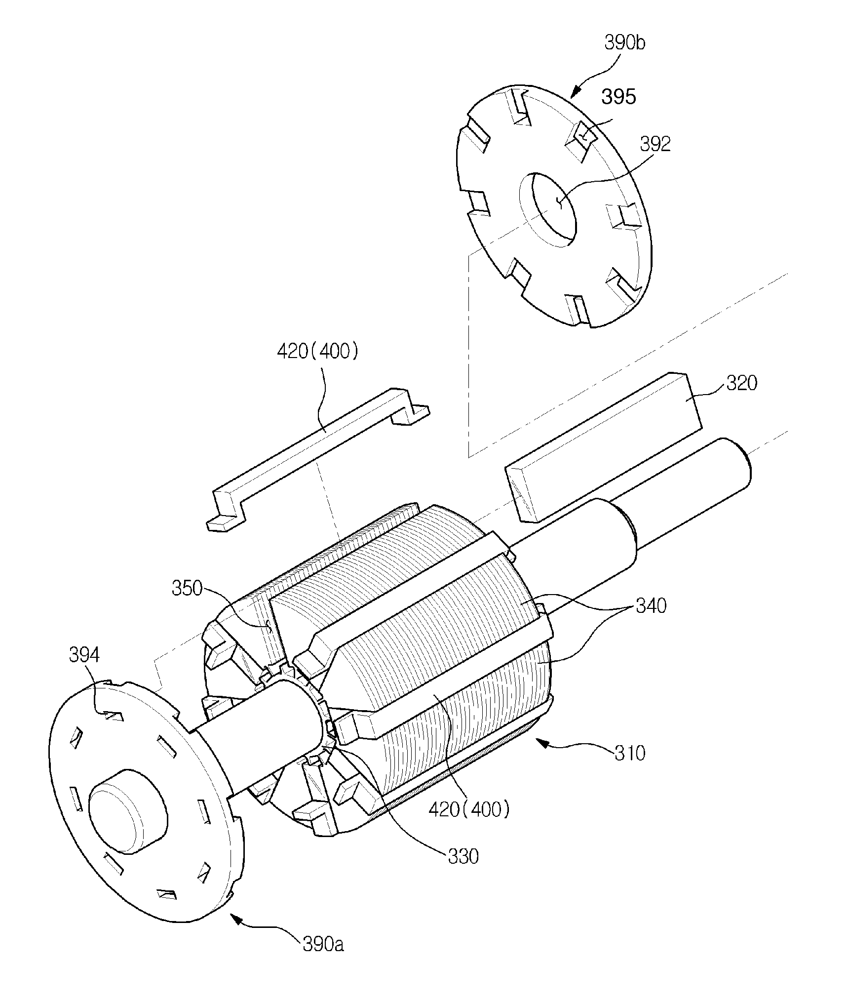
[0051]Hereinafter, embodiments of the present invention will be described with reference to the accompanying drawings. In the following description, “axial direction X” refers to a direction parallel to a motor shaft, for example, as shown in FIG. 1. “Circumferential direction C” refers to a direction extending along the circumference of a circle, and “radial direction R” refers to a direction extending along the radius of the circle.

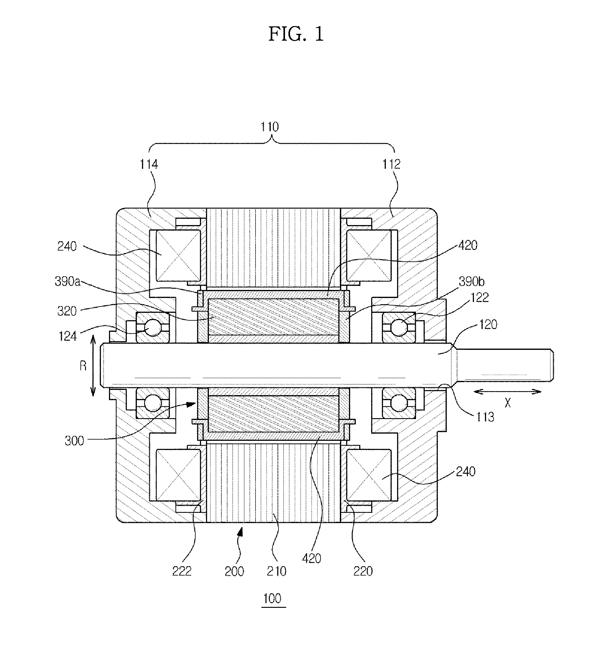
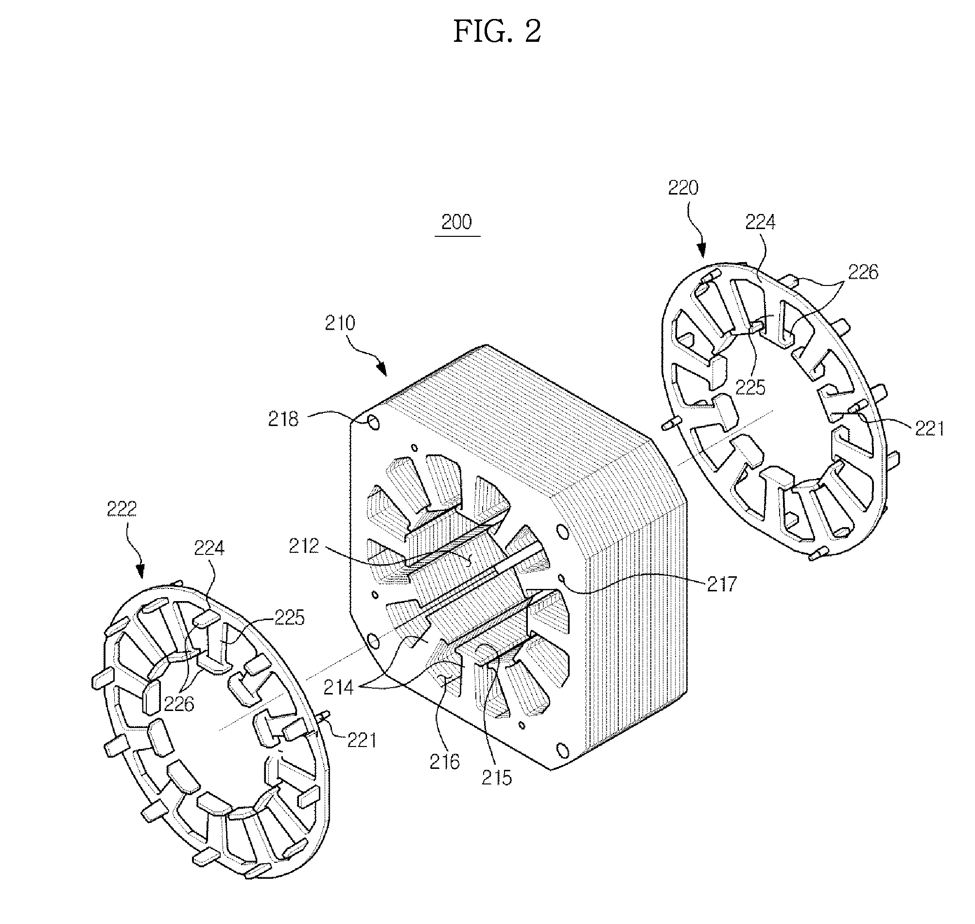
[0052]Referring to FIG. 1, a motor 100 is illustrated. The motor 100 includes a motor housing 110 to form an outer appearance of the motor 100. The motor housing 110 may include a first housing 112 and a second housing 114, which are separated from each other in an axial direction of the motor 100. The first housing 112 and second housing 114 may be fastened to a stator 200.

[0053]The stator 200 is disposed within the motor housing 110, along with a rotor 300. The stator 200 may be fixed to the motor housing 110. The rotor 300 is configured to co-operate...


PUM


Abstract

A rotor having an improved structure capable of achieving enhanced durability is disposed in a motor, the rotor including a sleeve having a shaft hole, through which a motor shaft extends, rotor cores spaced apart from one another in a circumferential direction of the rotor, and permanent magnets each disposed between adjacent ones of the rotor cores such that the permanent magnets are arranged in a radial manner about the sleeve. First and second cover plates may be disposed at opposite sides of the permanent magnets in an axial direction. Each of the first and second cover plates may include a shaft receiving hole to receive the motor shaft. The rotor may include a plurality of support members each having a magnet support portion arranged to support an outer end of a corresponding one of the permanent magnets in a radial direction of the rotor.

Description

CROSS-REFERENCE TO RELATED APPLICATIONS[0001]This application claims the priority benefit of Korean Patent Application No. 10-2012-0006425, filed on Jan. 19, 2012, in the Korean Intellectual Property Office, the disclosure of which is incorporated herein by reference.BACKGROUND[0002]1. Field[0003]Embodiments disclosed herein relate to a motor having an improved structure capable of achieving an enhanced durability.[0004]2. Description of the Related Art[0005]A motor is a machine which may obtain rotating force through electrical energy. In general, a motor includes a stator and a rotor. The rotor is configured to co-operate with the stator in an electromagnetic manner. The rotor is rotated by a force exerted between a magnetic field and current flowing through a coil.[0006]Permanent magnet motors, which use permanent magnets to generate an electric field, may be classified into a surface mounted permanent magnet motor, an interior type permanent magnet motor, and a spoke type perman...

Claims


Application Information

Patent Timeline
Patent Type & Authority Applications(United States)
IPC IPC(8): H02K1/28
CPCH02K1/28H02K1/278H02K1/2773H02K1/22
Inventor LEE, JAE YOUNGAN, YOUNG GYUKIM, DEOK JINKIM, YOUNG KWANIN, BYUNG RYELHAN, JIN WOO
Owner SAMSUNG ELECTRONICS CO LTD
Why Eureka
Try Eureka