Balance with inertia adjustment using an insert

Active Publication Date: 2013-07-25
NIVAROX FAR
View PDF7 Cites 21 Cited by
  • Summary
  • Abstract
  • Description
  • Claims
  • Application Information

AI Technical Summary

Benefits of technology

[0039]With the preferred use of silicon a balance structure is obtained which is both very light and very rigid, and which may be honeycombed in the area of the joint between the hub and the felloe. Transferring inserts,

Problems solved by technology

It is not therefore possible to use conventional technology, or solutions with lighter balances such as the balances wherein the felloe has spokes (?) disclosed in FR Patent No. 1275 357 in the name of Straumann, or FR Patent No. 1 301 938 in the name of LIP.
Indeed, even the redu

Method used


Image

  • Balance with inertia adjustment using an insert
  • Balance with inertia adjustment using an insert
  • Balance with inertia adjustment using an insert

Examples


Example

[0079]In a first embodiment, elastic holding means 10 is located on balance 1. Insert 7 may then either be rigid or elastic.

[0080]In an advantageous embodiment, at least one of recesses 8 comprised in balance 1 includes elastic holding means 10 for holding this insert 7 in recess 8 after the insertion of said insert therein. Preferably, several of these recesses 8, and preferably even all of them, comprise this elastic holding means 10, which may be arranged in different variants which will be described below. The properties of silicon, when balance 1 is made of this material, are particularly suited to forming elastic holding means 10 incorporated in the body of balance 1.

Example

[0081]In a second embodiment, the elastic holding means 10 is located on insert 7.

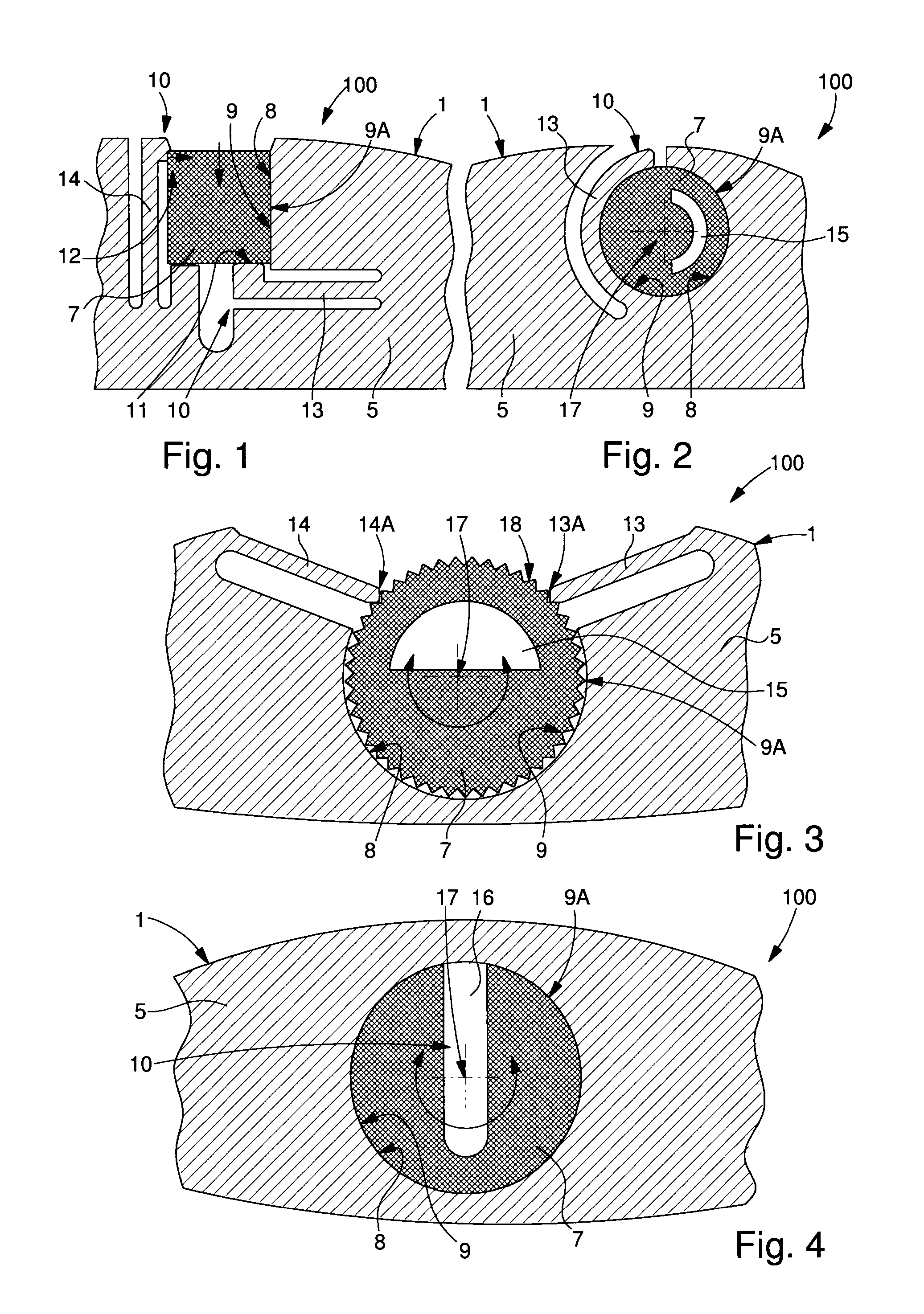
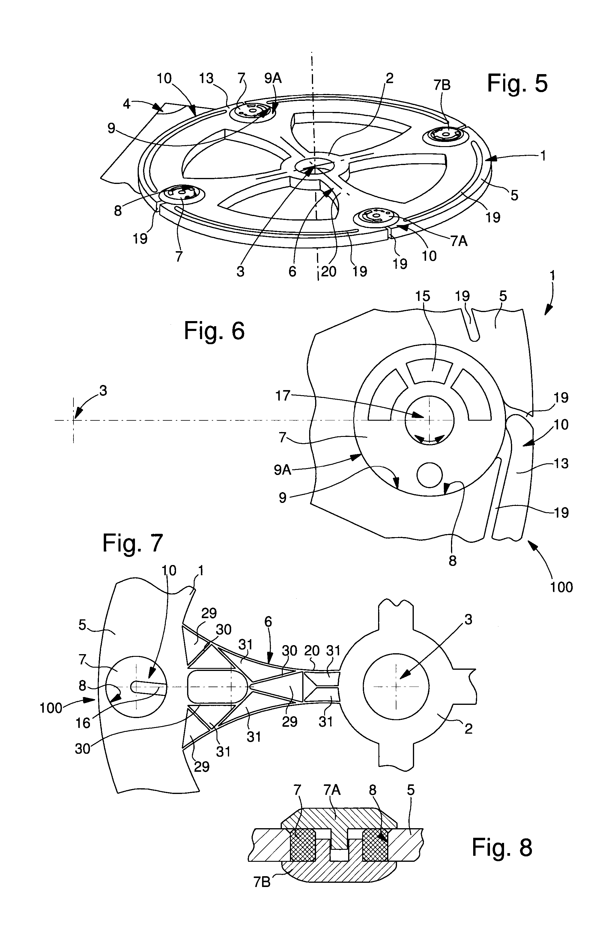
[0082]Elastic holding means 10 is then made on the insert or inserts 7, balance set 100 then includes a balance 1, which differs from that of the first embodiment in that it includes, at the periphery of felloe 5, at least one recess 8 for receiving at least one insert 7, and in that recess 8 does not necessarily include elastic holding means. Indeed, in this second embodiment, it is insert 7 which includes elastic holding means 10 for holding said insert in recess 8 after its insertion therein, as seen in FIG. 4, or in FIG. 7, where insert 7 includes a slot 16 which gives it sufficient flexibility. This insert 7 thus forms a slit inertia-block having an unbalance, due to slot 16, and this configuration means that one part can be fitted to the other, without forcing balance 1 beyond breaking point, especially when said balance is made of silicon or similar. This slot 16 is also advantageously used for ...

Example

[0083]In a third embodiment which is not shown in the Figures, the elastic holding means 10 is made both on balance 1 and on insert(s) 7. Insert 7 then includes this type of holding means 10 and recess 8 also includes elastic holding means 10 for holding insert 7 in recess 8 after its insertion therein.

[0084]In the three embodiments, recesses 8, inserts 7 and elastic holding means 10 may take different configurations, including certain preferred and non-limiting configurations which are explained below.

[0085]Preferably, elastic holding means 10 is made in felloe 5 of balance 1.

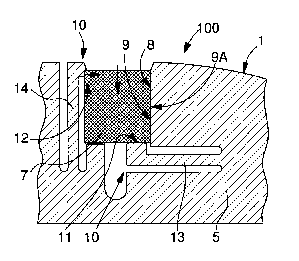
[0086]In a first radial configuration, illustrated by the first variant of FIG. 1 or by the sixth variant of FIG. 11, elastic holding means 10 is arranged, preferably made in felloe 5, to hold insert 7 in recess 8 in a radial direction relative to balance staff 3, particularly for a radial adjustment of insert 7.

[0087]Preferably, as seen in FIG. 1, insert 7 is held in this radial direction, elastic holding mea...


PUM

PropertyMeasurementUnit
Angleaaaaaaaaaa
Elasticityaaaaaaaaaa
Stress optical coefficientaaaaaaaaaa

Abstract

A balance set for a timepiece, with inertia adjustment for adjusting inertia and/or balancing and/or oscillation frequency of the balance, with a balance including an insert inserted into a recess of a felloe connected to a hub by a joining surface. The balance includes on the felloe thereof an elastic holding mechanism including two antagonistic elastic lips which, when stressed, allow insertion of the insert into the recess and which, when released, prevent removal of the insert from the recess. A sprung balance or a timepiece can incorporate such a balance.

Description

FIELD OF THE INVENTION[0001]The invention concerns a method of making a balance set for a timepiece, with inertia adjustment for adjusting the inertia and / or poising and / or oscillation frequency of the balance, comprising, on the one hand, a balance including a hub arranged to cooperate with a balance staff perpendicular to a balance plane, and a peripheral, continuous or discontinuous felloe, connected to said hub by at least one joining surface, said balance set comprising, on the other hand, at least one insert. Said balance further comprises, at the periphery of said felloe, at least one recess for receiving said at least one insert, said insert comprising a complementary guide means, whose profile is complementary to a guide means comprised in said recess.[0002]The invention further concerns a balance for a timepiece, with inertia adjustment for adjusting the inertia and / or poising and / or oscillation frequency of the balance, designed for a balance set of this type, and includi...

Claims


Application Information

Patent Timeline
IPC IPC(8): G04B17/20
CPCG04B17/063G04B18/006Y10T29/49826G04B17/20G04B17/222G04B17/06G04B18/00
Inventor MALLET, DANIELTOLLE, FREDERICBARTHOULOT, PHILIPPEVICENTE, DANIELGRAF, EMMANUELBERGER, PHILOMENECUSIN, PIERRE
Owner NIVAROX FAR
Why Eureka
Try Eureka