System and method for radiation detection and imaging

Active Publication Date: 2007-12-13
TEXAS INSTR INC
View PDF7 Cites 0 Cited by
  • Summary
  • Abstract
  • Description
  • Claims
  • Application Information

AI Technical Summary

Benefits of technology

[0012]An advantage of a preferred embodiment of the present invention is that a thermal sensor array can be created with low thermal mass, which can improve the response time of the thermal sensor array. The improved response time can yield better radiation detection and imaging performance.
[0013]A further advantage of a preferred embodiment of the present invention is that a thermal sensor array can be created with a high fill factor. The t

Problems solved by technology

However, if the sensor is too well isolated, the heat will not dissipate fast enough, therefore extending the response time of the thermal sensor.
One disadvantage of the prior art is that the design of the pixels, although yielding good thermal performance, has a poor fill factor for the thermal sensor array due to the underlying support structure of the pixels, such as the legs 110, the rim 160, and the serpentines 165, consuming a significant amount of integrated ci

Method used


Image

  • System and method for radiation detection and imaging
  • System and method for radiation detection and imaging
  • System and method for radiation detection and imaging

Examples


Example

[0024]The making and using of the presently preferred embodiments are discussed in detail below. It should be appreciated, however, that the present invention provides many applicable inventive concepts that can be embodied in a wide variety of specific contexts. The specific embodiments discussed are merely illustrative of specific ways to make and use the invention, and do not limit the scope of the invention.

[0025]The present invention will be described with respect to preferred embodiments in a specific context, namely a high fill factor thermal sensor array with a low thermal mass and fast response time. The size of each thermal sensor pixel in the thermal sensor array can be scaled without incurring dramatic increases in cost or manufacturing difficulty. These thermal sensor arrays may be referred to as micro electromechanical systems.

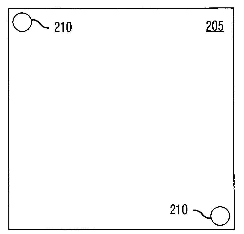
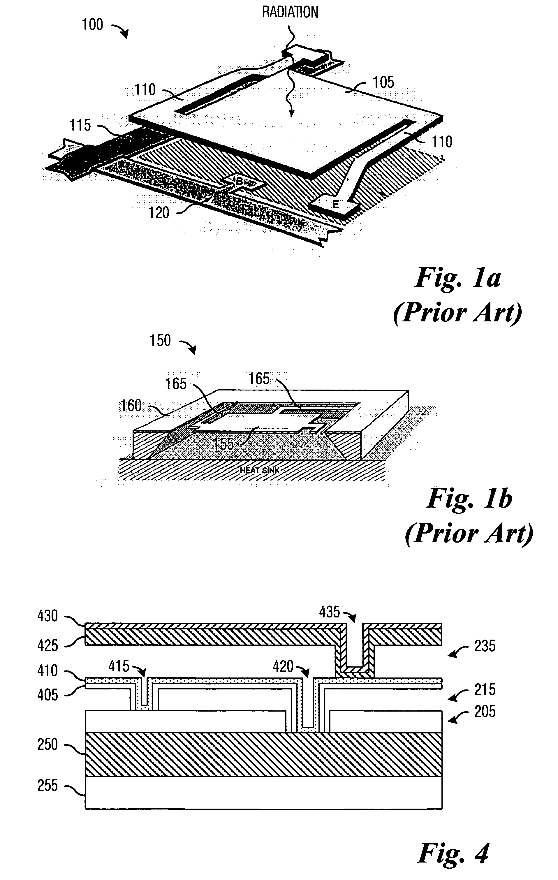
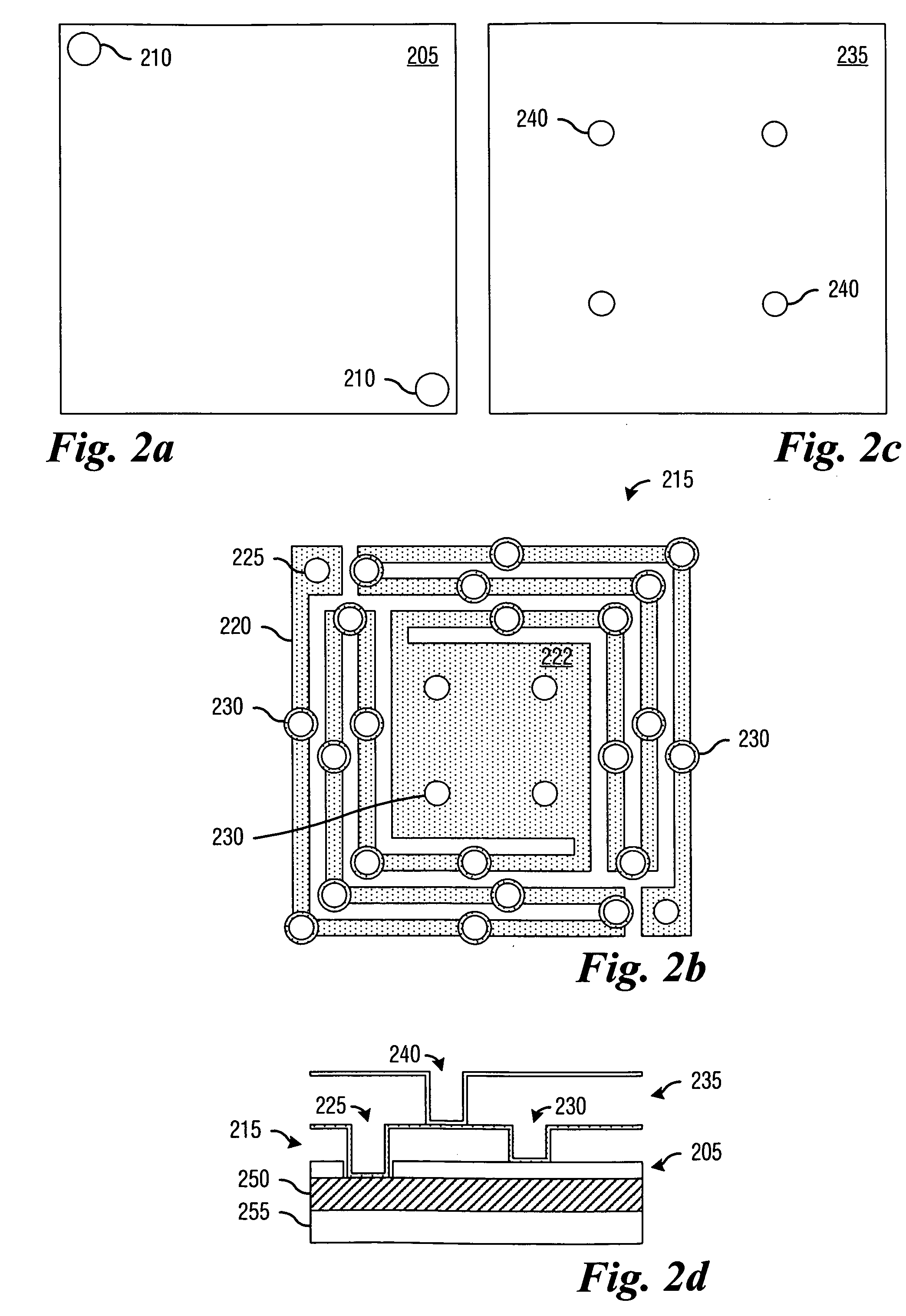
[0026]With reference now to FIGS. 2a through 2d, there are shown diagrams illustrating a cross-sectional view of a single pixel of a thermal sen...


PUM


Abstract

System and method for detecting and imaging radiation. A preferred embodiment comprises a substrate with electronic circuitry to detect changes in a transduction signal, an intermediate conductive layer disposed above and electrically connected to the electronic circuitry, and a lower separation layer with a high coefficient of thermal resistance that partially separates the intermediate conductive layer from the electronic circuitry. The preferred embodiment also includes a top layer disposed above the intermediate conductive layer and an absorptive layer overlying the top layer, with the absorptive layer being electrically connected to the intermediate conductive layer. The absorptive layer produces a transduction signal that is proportional to an amount of radiation incident on the absorptive layer. The vertical fabrication of the radiation sensor allows for sensor arrays with a good fill factor, permitting the creation of sensor arrays with high resolution while maintaining low costs.

Description

TECHNICAL FIELD[0001]The present invention relates generally to a system and a method for integrated circuits, and more particularly to a system and a method for detecting and imaging radiation.BACKGROUND[0002]It is possible to detect radiation, such as infrared (IR) radiation, using one of two general types of sensors. A first sensor type (photon sensor) detects the presence of the radiation by detecting the direct interaction of the radiation with the atomic lattice of the sensing material in the sensor, and a second sensor type (thermal sensor) detects the radiation by detecting a temperature change in the sensor due to the absorbed radiation. The temperature change causes a physical parameter of the sensor, such as resistance or voltage, to change and therefore can be detected by electronic circuitry.[0003]With thermal sensors, thermal mass (MTH) and thermal conductivity (CTH) determine the response time of the system, where the response time is proportional to MTH / CTH. Generall...

Claims


Application Information

Patent Timeline
IPC IPC(8): G01J5/00
CPCG01J5/20G01J5/023G01J5/024
Inventor ODEN, PATRICK IANNEIDRICH, JASON MICHAEL
Owner TEXAS INSTR INC
Why Eureka
Try Eureka