Porous blocker bar for plate-fin heat exchanger

a technology of heat exchangers and blockers, which is applied in indirect heat exchangers, lighting and heating apparatus, instruments, etc., can solve the problems of fatigue at the hot/hot corner, degraded performance and/or operating life, etc., and achieve the effect of reducing thermal fatigue and improving thermal fatigue resistan

Active Publication Date: 2013-07-25
HONEYWELL INT INC
View PDF5 Cites 3 Cited by
  • Summary
  • Abstract
  • Description
  • Claims
  • Application Information

AI Technical Summary

Benefits of technology

[0003]Accordingly, there is a need for a heat exchanger with improved resistance to thermal fatigue.
[0004]In one aspect of the present invention, a plate-fin heat exchanger adapted to reduce thermal fatigue, includes a cold fluid pathway running along a first axis, a hot fluid pathway running along a second axis perpendicular to the first axis, and at least one porous blocker bar running along the first axis, where the porous blocker bar includes a set of pores adapted to control flow along the hot fluid pathway and coupled to an inlet of the hot fluid pathway.

Problems solved by technology

Such transient changes in temperature create gradients throughout the heat exchanger that may cause degraded performance and / or operating life due to thermal fatigue of tube sheets with the heat exchanger.
High-temperature heat exchangers may be especially susceptible to fatigue at the hot / hot corner (the corner at the hot inlet and cold outlet) and the hot / cold corner (the corner at the hot inlet and the cold inlet).

Method used


Image

  • Porous blocker bar for plate-fin heat exchanger
  • Porous blocker bar for plate-fin heat exchanger
  • Porous blocker bar for plate-fin heat exchanger

Examples


Embodiment Construction

[0014]The following detailed description is of the best currently contemplated modes of carrying out exemplary embodiments of the invention. The description is not to be taken in a limiting sense, but is made merely for the purpose of illustrating the general principles of the invention, since the scope of the invention is best defined by the appended claims.

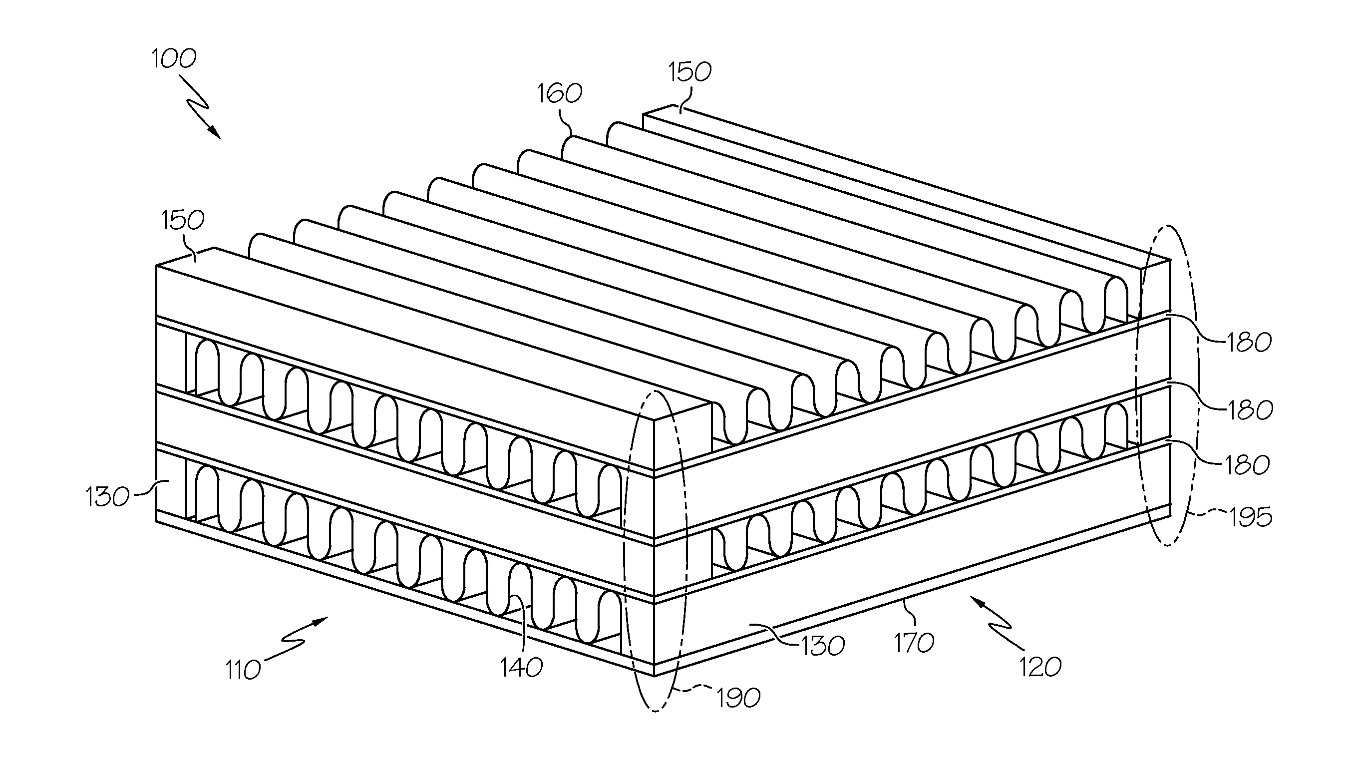
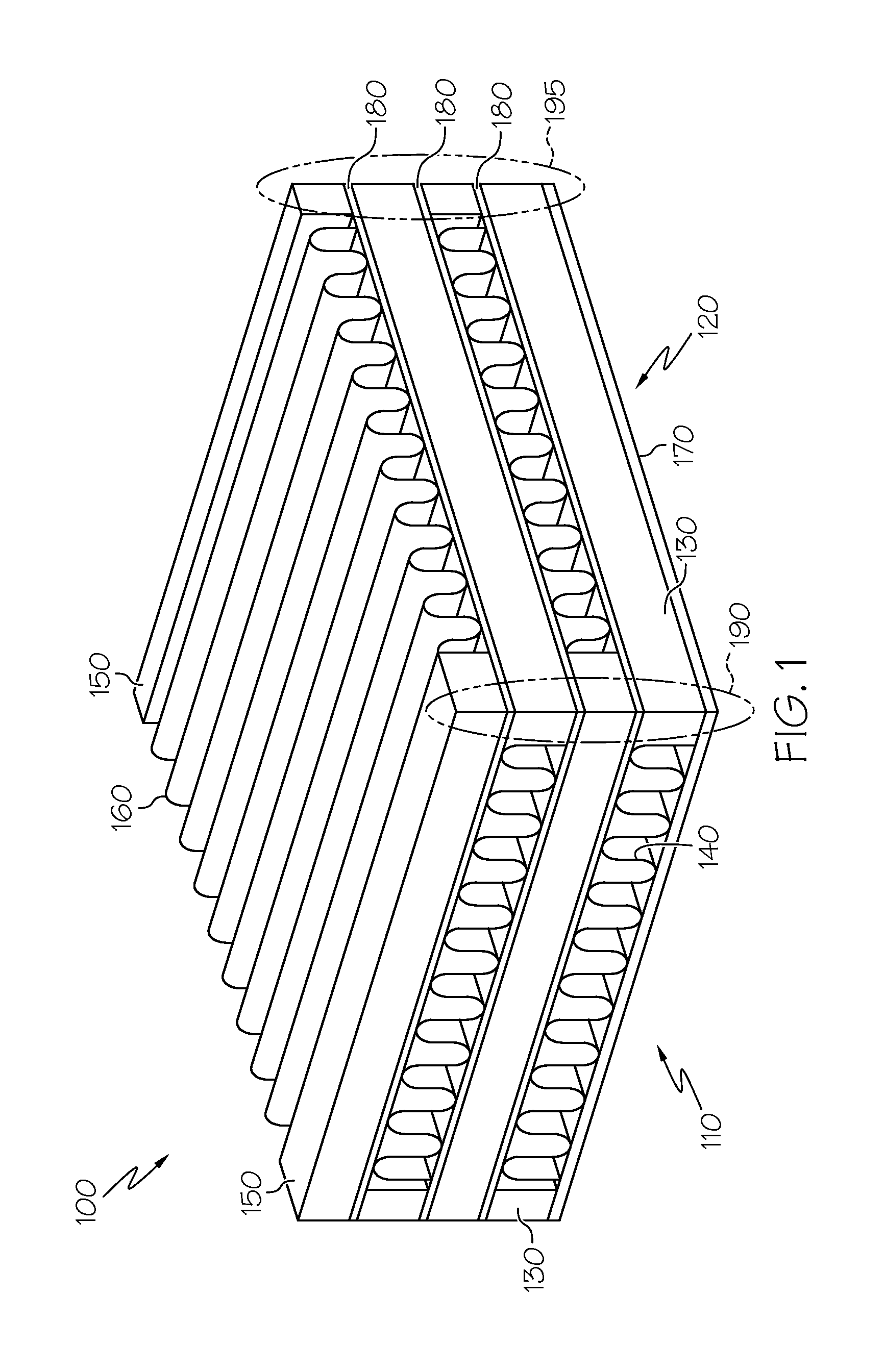
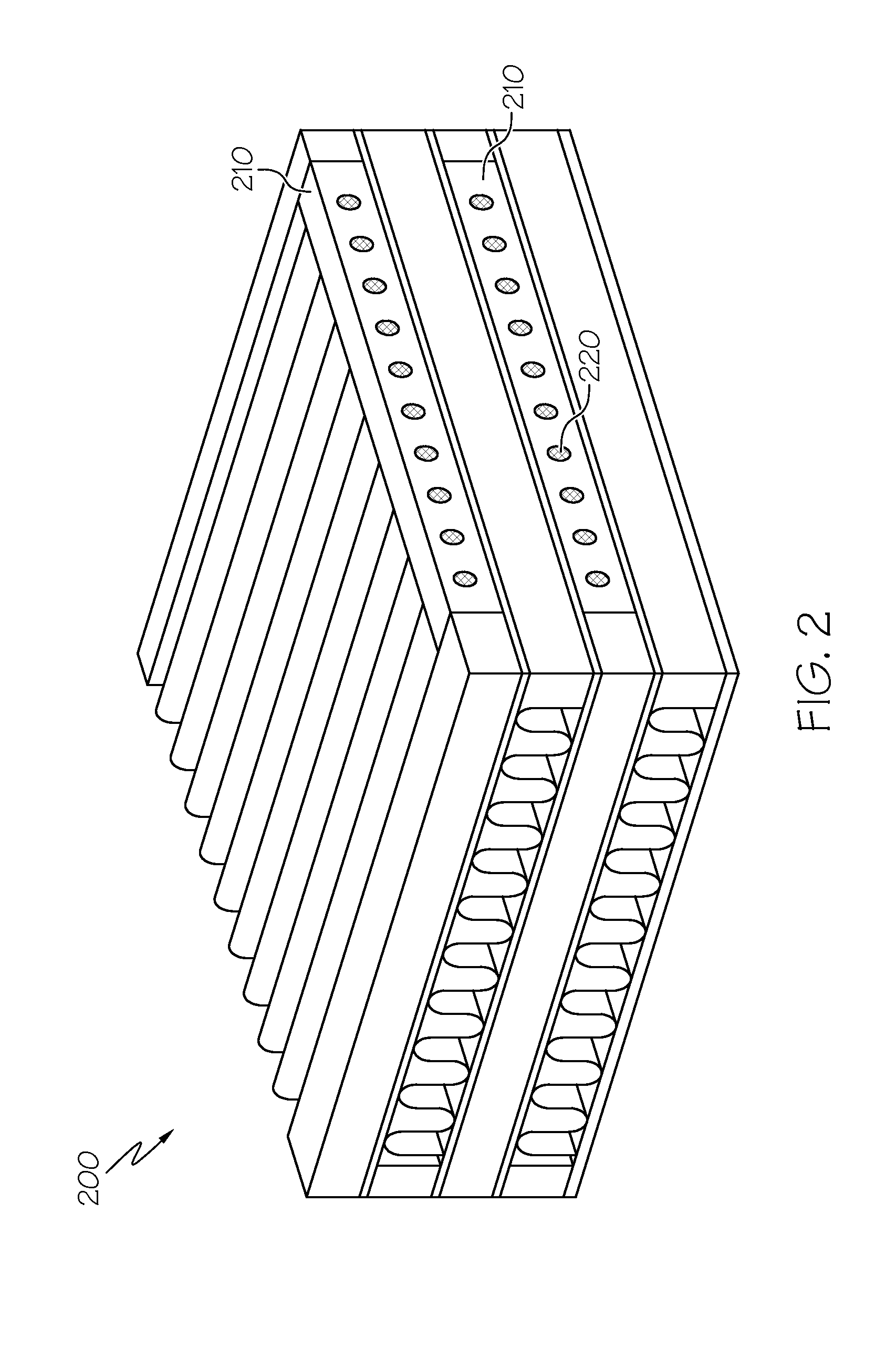
[0015]Various inventive features are described below that can each be used independently of one another or in combination with other features. Broadly, embodiments of the present invention generally provide a way to reduce fatigue experienced by components of a heat exchanger and improve temperature gradients within the heat exchanger. The porous blocker bars of the present invention may be configured such that structural integrity of the heat exchanger may be improved and hot flow may be reduced and / or dampened. In this manner, the operating life and performance of the heat exchanger may be improved.

[0016]FIG. 1 illustrates a p...


PUM


Abstract

A plate-fin heat exchanger adapted to reduce thermal fatigue is described. The plate-fin heat exchanger includes a cold fluid pathway running along a first axis, a hot fluid pathway running along a second axis perpendicular to the first axis, and at least one porous blocker bar running along the first axis. The porous blocker bar includes a set of pores adapted to control the flow along the hot fluid pathway and coupled to an inlet of the hot fluid pathway.

Description

BACKGROUND AND SUMMARY OF THE INVENTION[0001]The present invention generally relates to high-temperature plate-fin heat exchangers. Such heat exchangers may include a cold fluid pathway and a hot fluid pathway. The heat exchanger may be used to heat cold fluid (e.g., outside air) and / or cool hot fluid (e.g., cooling fluid from an engine). Plate-fin heat exchangers may operate with any combination of fluids (gas, liquid, or two-phase fluid). The hot fluid may include transient changes in temperature due to various operating conditions (e.g., increased heat from engine throttling).[0002]Such transient changes in temperature create gradients throughout the heat exchanger that may cause degraded performance and / or operating life due to thermal fatigue of tube sheets with the heat exchanger. High-temperature heat exchangers may be especially susceptible to fatigue at the hot / hot corner (the corner at the hot inlet and cold outlet) and the hot / cold corner (the corner at the hot inlet and ...

Claims


Application Information

Patent Timeline
Patent Type & Authority Applications(United States)
IPC IPC(8): G06F17/50F28F1/00F28D7/00
CPCF28F9/028F28D9/0062F28F13/003
Inventor BERUKHIM, DAVIDLEISHMAN, ANDREWAVANESSIAN, VAHE
Owner HONEYWELL INT INC
Why Eureka
Try Eureka