
Reservoir System for Gas Delivery to a Patient

a gas supply and patient technology, applied in the field of breathing systems, can solve problems such as ineffective solutions, and achieve the effect of facilitating drying

Active Publication Date: 2013-08-01
WESTMED
View PDF11 Cites 22 Cited by
  • Summary
  • Abstract
  • Description
  • Claims
  • Application Information

AI Technical Summary

Benefits of technology

The present invention relates to a self-inflating reservoir for patients with breathing difficulties. The reservoir is made of a flexible material that returns to its original shape after compression caused by inhalation. The reservoir includes a flange to support it in an inverted position for easy drying, and may also include stiffening members to prevent collapse when inverted. The negative pressure created by the reservoir as it rebounds helps to fill it and keep the inlet check valve closed during patient exhalation and dwell time. The technical effects of the invention are improved respiratory therapy and easier drying of the reservoir.

Problems solved by technology

In other words, any structure or component added, altered, or selectively altered for purposes of increasing the internal resistance to gas flow toward the outlet port must not be positioned between a patient interface, i.e., a mouth piece or mask, and the outlet port, otherwise the solution will be ineffective as the gas will vent to atmosphere through the outlet port.

Method used


Image

  • Reservoir System for Gas Delivery to a Patient
  • Reservoir System for Gas Delivery to a Patient
  • Reservoir System for Gas Delivery to a Patient

Examples


Embodiment Construction

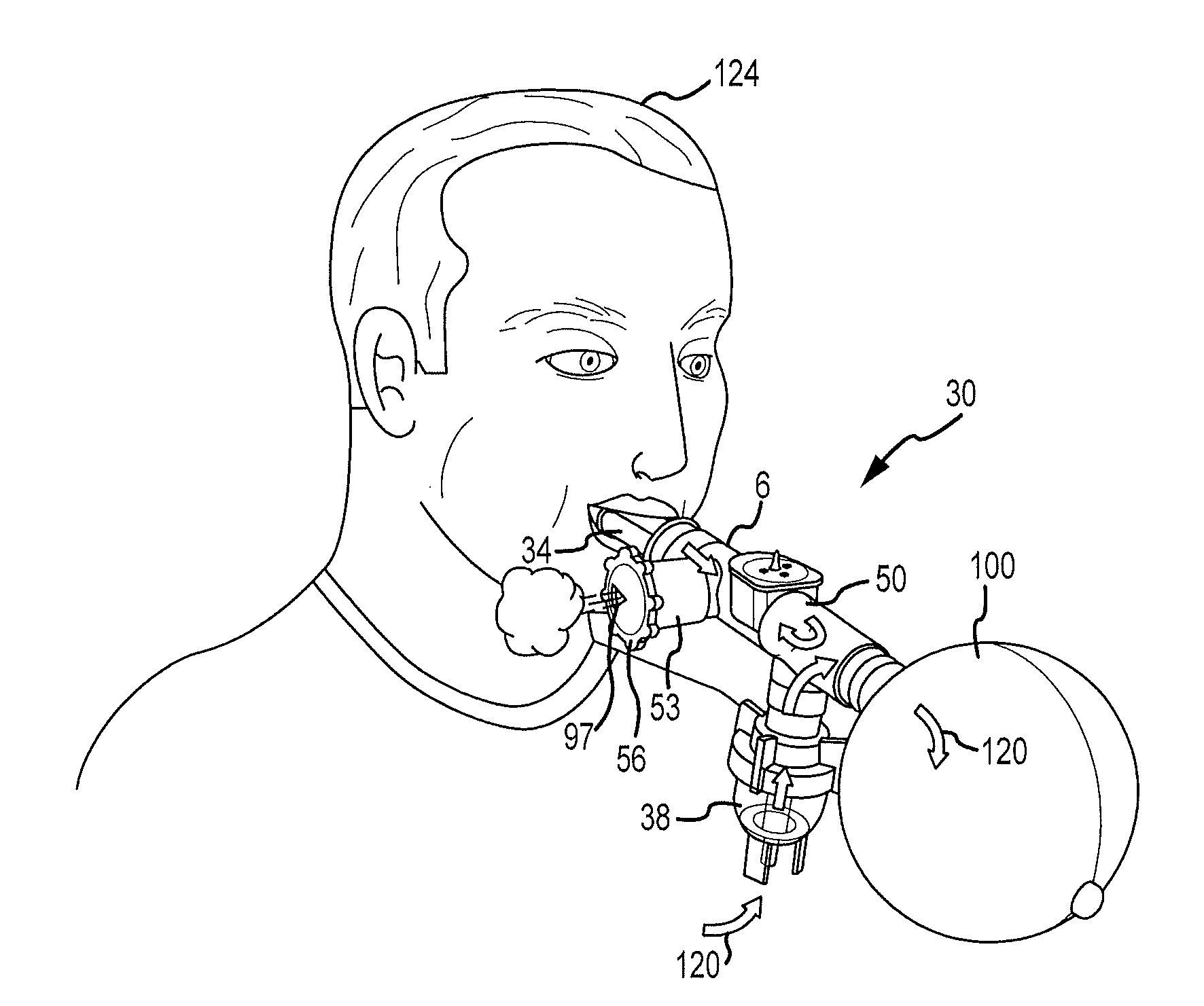
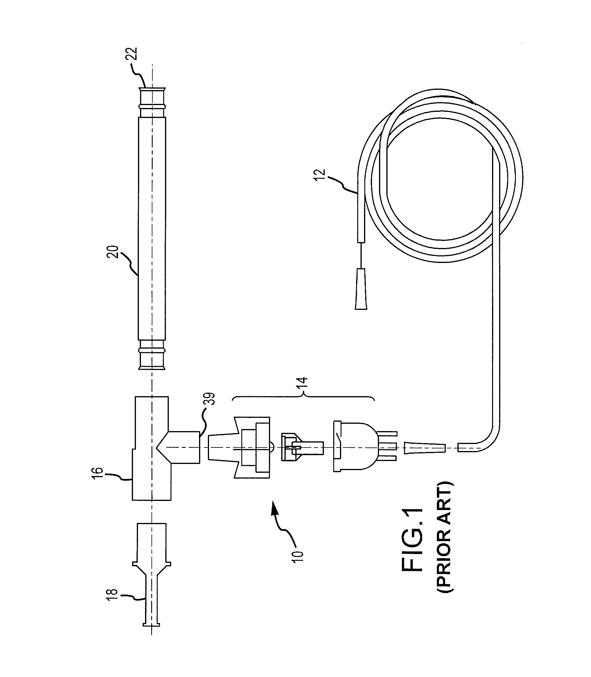
[0034]FIG. 1 is an example of a current commercial aerosol delivery system 10 that does not employ a reservoir bag or one-way valving system. Oxygen flows though supply tubing 12 to the nebulizer 14 that adds medicine to the oxygen to create a gas comprised of aerosolized gas. The gas travels through housing 16 and mouth piece 18 toward the patient, into a tube 20 or both, depending upon the dynamic internal system pressures. The mouth piece 18 may be replaced by a mask 14 as shown in FIG. 4. The tube 20 may act as a reservoir wherein inhalation will draw gas from the tube 20, through the housing 16 and to the mouth piece 18 as well as from the nebulizer 14. Upon exhalation, the exhaled gases flow out through the mouth piece 18 and housing 16 into the tube 20 and ultimately into atmosphere through outlet port 22 of the tube 20. During any period of time when the patient is not inhaling, the aerosol mixture from the nebulizer 14 will flow toward the mouth piece 18 and toward the outl...


PUM


Abstract

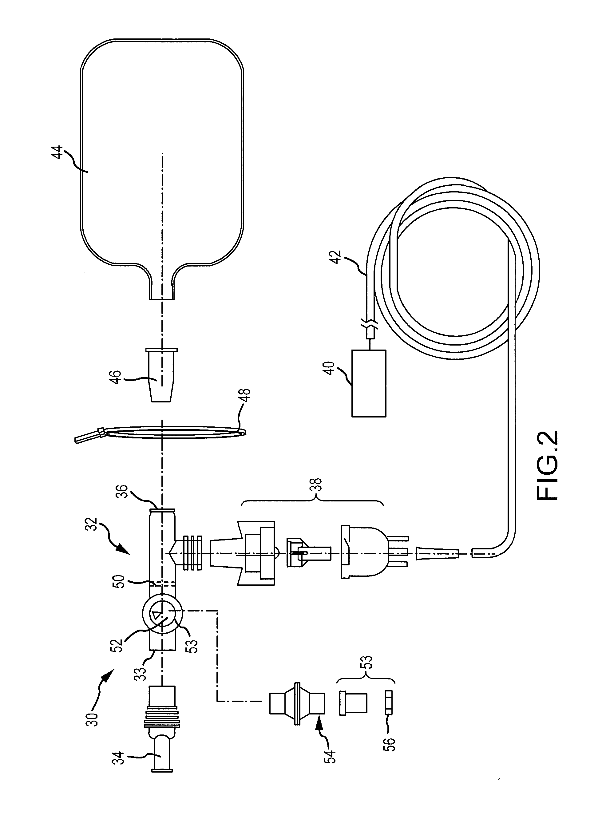
A breathing system is provided that employs a reservoir for holding oxygen or an oxygen and medicine mixture while the patient is not inhaling. The reservoir generally prevents waste and reduces cost and helps prevent the patient from re-inhaling the previously exhaled gases. The reservoir also may include a flange extending from an inlet thereof that allows the reservoir to be positioned in an inverted position.

Description

CROSS-REFERENCE TO RELATED APPLICATION[0001]This application is a Continuation-In-Part of U.S. patent Ser. No. 13 / 188,793, filed Jul. 22, 2011, which is a Continuation-In-Part of U.S. patent Ser. No. 12 / 688,295, filed Jan. 15, 2010, which claims the benefit of U.S. Provisional Application Ser. No. 61 / 145,318, filed Jan. 16, 2009, the entirety of each application being incorporated by reference herein.FIELD OF THE INVENTION[0002]Embodiments of the present invention generally relate to a breathing system designed to provide gas, such as an oxygen and medicine mixture, to a patient.BACKGROUND OF THE INVENTION[0003]Hospitalized patients with pulmonary or cardiovascular health issues often require supplemental oxygen. Typically, supplemental oxygen is delivered to a patient from an oxygen source that is interconnected by tubing to a patient interface, e.g., a mouth piece or a mask. In addition, some patients require medicine, which is delivered to the patient in the form of aerosolized p...

Claims


Application Information

Patent Timeline
Patent Type & Authority Applications(United States)
IPC IPC(8): A61M16/00A61M16/06A61B5/087A61M16/20A61M16/12A61M16/08A61M16/10A61M16/04A61M16/14
CPCA61M16/0078A61M16/1065A61M16/06A61B5/087A61M16/14A61M16/12A61M16/0875A61M16/1055A61M16/208A61M11/06A61M15/0086A61M16/0816A61M2202/0208A61M2207/00A61M16/0866A61M16/125A61M15/0016A61M15/0018A61M16/0084A61M16/0488A61M16/101
Inventor MCKINNON, ROBERT J.BICKLEY, JAMES DALE
Owner WESTMED
Learn More