Breathing system with flow estimation

a flow estimation and breathing system technology, applied in the field of breathing systems, can solve the problems of increasing the flow resistance of the breathing system, adding a dead volume, and difficulty in handling moisture and mucus from the patient, and achieve the effect of accurate control of the inspiratory and expiratory breathing cycles

Active Publication Date: 2013-08-01
MAQUET CRITICAL CARE
View PDF15 Cites 11 Cited by
  • Summary
  • Abstract
  • Description
  • Claims
  • Application Information

AI Technical Summary

Benefits of technology

[0019]Some embodiments provide for determining the actual gas flow at various locations in the breathing system. This has several advantages. There is a need of having an accurate control of the inspiratory and expiratory breathing cycles. Determining the correct flow for example at a patient interface, such as a patient tube or mask would advantageously allow correct control of such breathing cycles. For instance, it is desirable to detect when the expiratory flow from the patient is zero for controlling a correct frequency of the breathing cycle. Another example is in pressure support control, when a gas flow threshold is defined for triggering the next cycle. Determining the actual patient gas flow allows a correct threshold to be defined.

Problems solved by technology

However, this adds a dead volume and may increase the flow resistance in the breathing system.
Further problems with flow meters at the y-piece include difficulties in handling moisture and mucus from the patient, quick temperature changes between expiratory and inspiratory gas, and varying gas compositions, e.g. of CO2 and anesthetic agent.
An erroneous estimation of flow in breathing devices may involve a safety hazard potentially exposing a connected patient to situations with dire consequences, e.g. when a non-desired amount of a substance is delivered to the patient.
A source for incorrect estimation and regulation of the gas flow is the compressible internal volume of the breathing system which affects the actual gas flow, for example at a patient connection.
Having an increased number of measuring points in the breathing system do still not compensate for the actual compressive volume effect.
Also, flow meters are expensive and have inherent drawbacks depending on measuring technique.

Method used


Image

  • Breathing system with flow estimation
  • Breathing system with flow estimation
  • Breathing system with flow estimation

Examples


Embodiment Construction

[0029]Specific embodiments of the invention will now be described with reference to the accompanying drawings. This invention may, however, be embodied in many different forms and should not be construed as limited to the embodiments set forth herein; rather, these embodiments are provided so that this disclosure will be thorough and complete, and will fully convey the scope of the invention to those skilled in the art. The terminology used in the detailed description of the embodiments illustrated in the accompanying drawings is not intended to be limiting of the invention. In the drawings, like numbers refer to like elements.

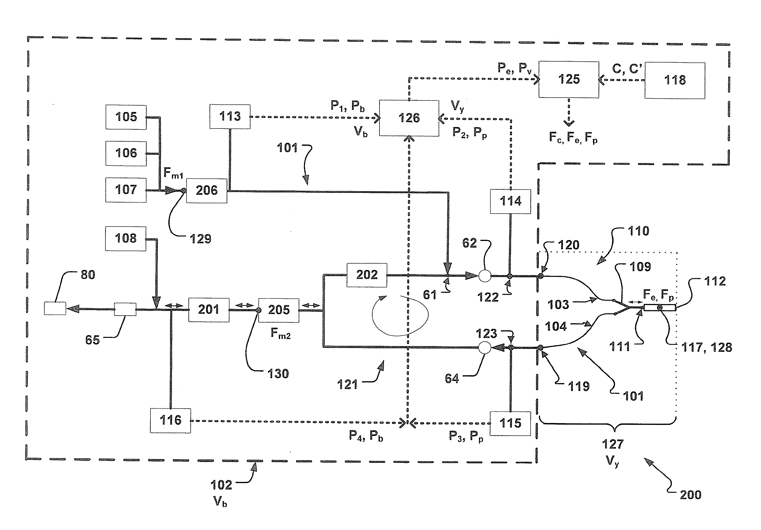
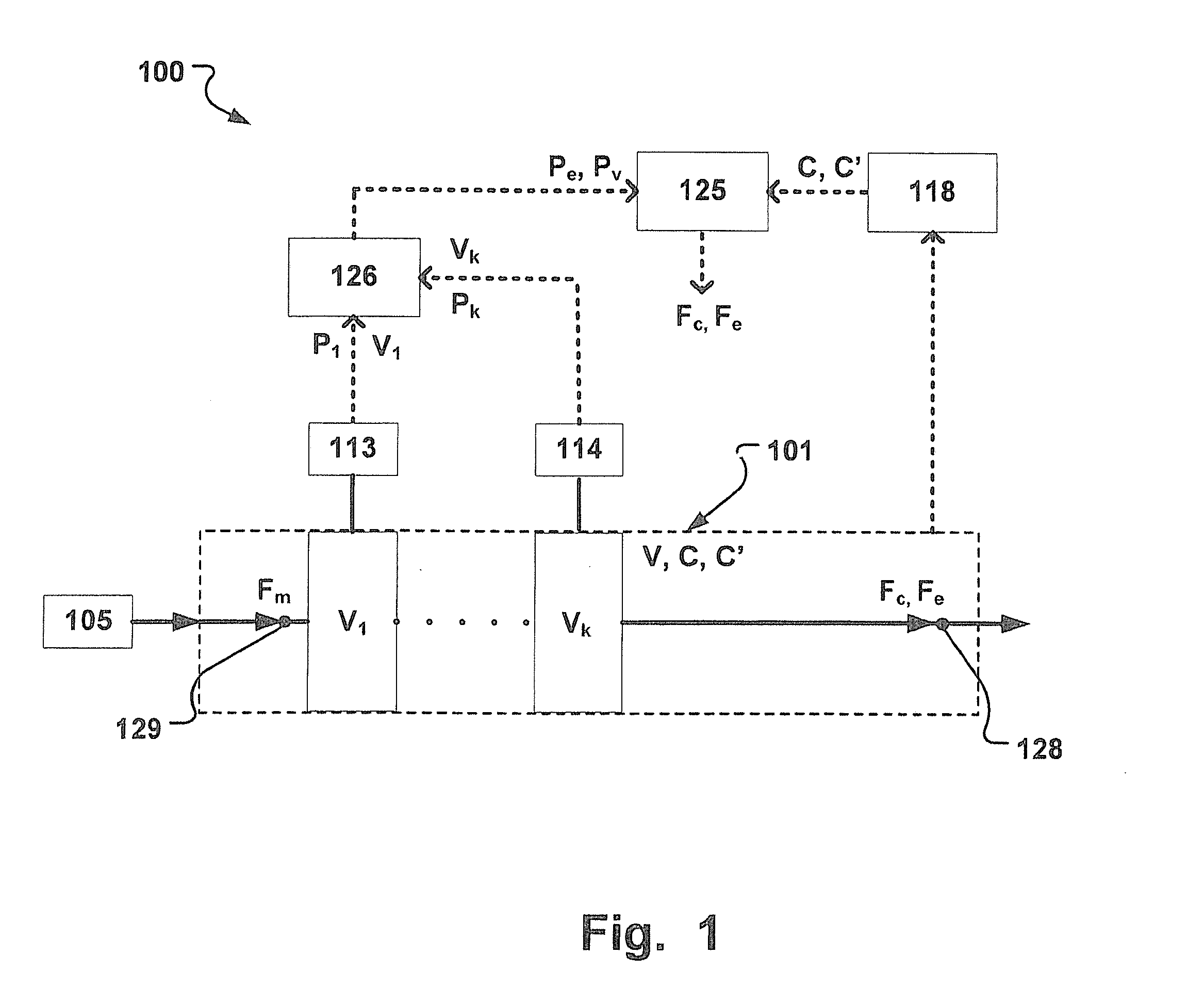
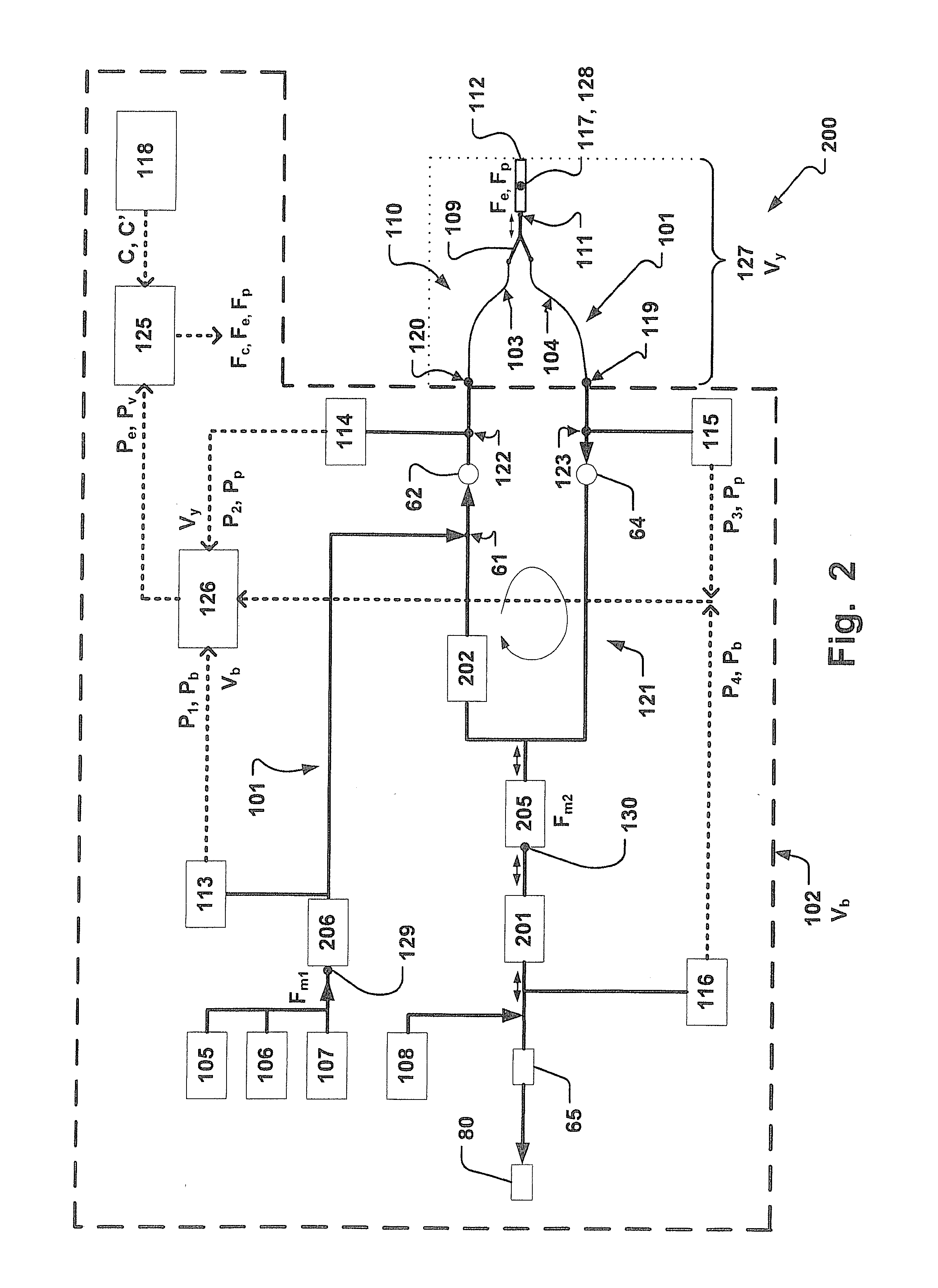
[0030]The following description focuses on an embodiment of the present invention applicable to an anesthesia machine and in particular to an anesthesia machine having a circle system. However, it will be appreciated that the invention is not limited to this application but may be applied to many other breathing apparatuses, including for example intensive car...


PUM


Abstract

A breathing system for ventilating a patient has a gas channel enclosing a gas channel volume (V), and a compliance (C). The system has a flow calculation unit operative to determine a gas flow estimate (Fe) at a flow estimate location in the gas channel. The gas flow estimate (Fe) is based on a relationship between a monitored gas flow (Fm) in the gas channel and a compressible gas flow (Fc) which depends on the compliance (C) in the gas channel. The monitored gas flow (Fm) is a gas flow at a monitoring location in the gas channel and the compressible gas flow (Fc) is a flow of gas in the gas channel between the flow estimate location and the monitoring location, and the flow estimate location is remote from the monitoring location.

Description

BACKGROUND OF THE INVENTION[0001]1. Field of the Invention[0002]This invention pertains in general to the field of breathing systems for providing a flow of gas to a patient.[0003]More precisely, the invention relates to determining the actual flow in such breathing systems for safety purposes.[0004]2. Description of the Prior Art[0005]Various breathing systems for regulating a flow of gas to a patient are known. Such breathing systems include for instance anesthesia machines, intensive care ventilators with added anesthesia capabilities, etc.[0006]Conventional breathing systems have a flow meter at a location where it is desired to measure the gas flow. However, this adds a dead volume and may increase the flow resistance in the breathing system. Further problems with flow meters at the y-piece include difficulties in handling moisture and mucus from the patient, quick temperature changes between expiratory and inspiratory gas, and varying gas compositions, e.g. of CO2 and anesthet...

Claims


Application Information

Patent Timeline
Patent Type & Authority Applications(United States)
IPC IPC(8): A61M16/00A61M16/04A61M16/06A61M16/08
CPCA61M16/0051A61M2016/0021A61M2016/0036A61M2230/46A61M16/0875A61M16/04A61M16/06A61M16/0816A61M16/0057A61M2016/0027A61M16/0833A61M16/026A61M2205/3331A61M2205/3344A61M2205/3334
Inventor EKLUND, MATHIASMAGNUS, HALLBACK
Owner MAQUET CRITICAL CARE
Why Eureka
Try Eureka