

Backlight module and display device including the same
a backlight module and display device technology, applied in the field of backlight modules, can solve problems such as unfavorable nois
- Summary
- Abstract
- Description
- Claims
- Application Information
AI Technical Summary
Benefits of technology
Problems solved by technology
Method used
Image

Examples
first embodiment
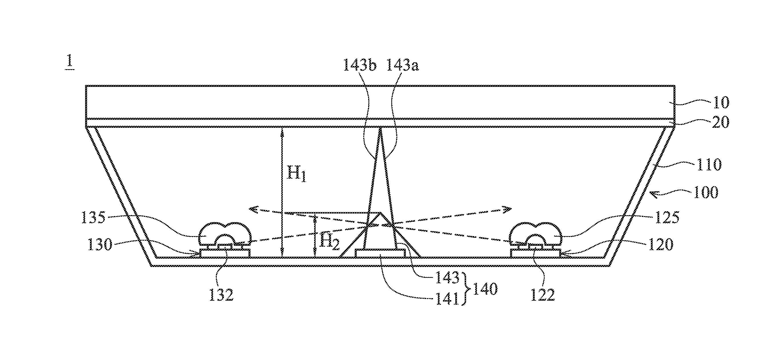
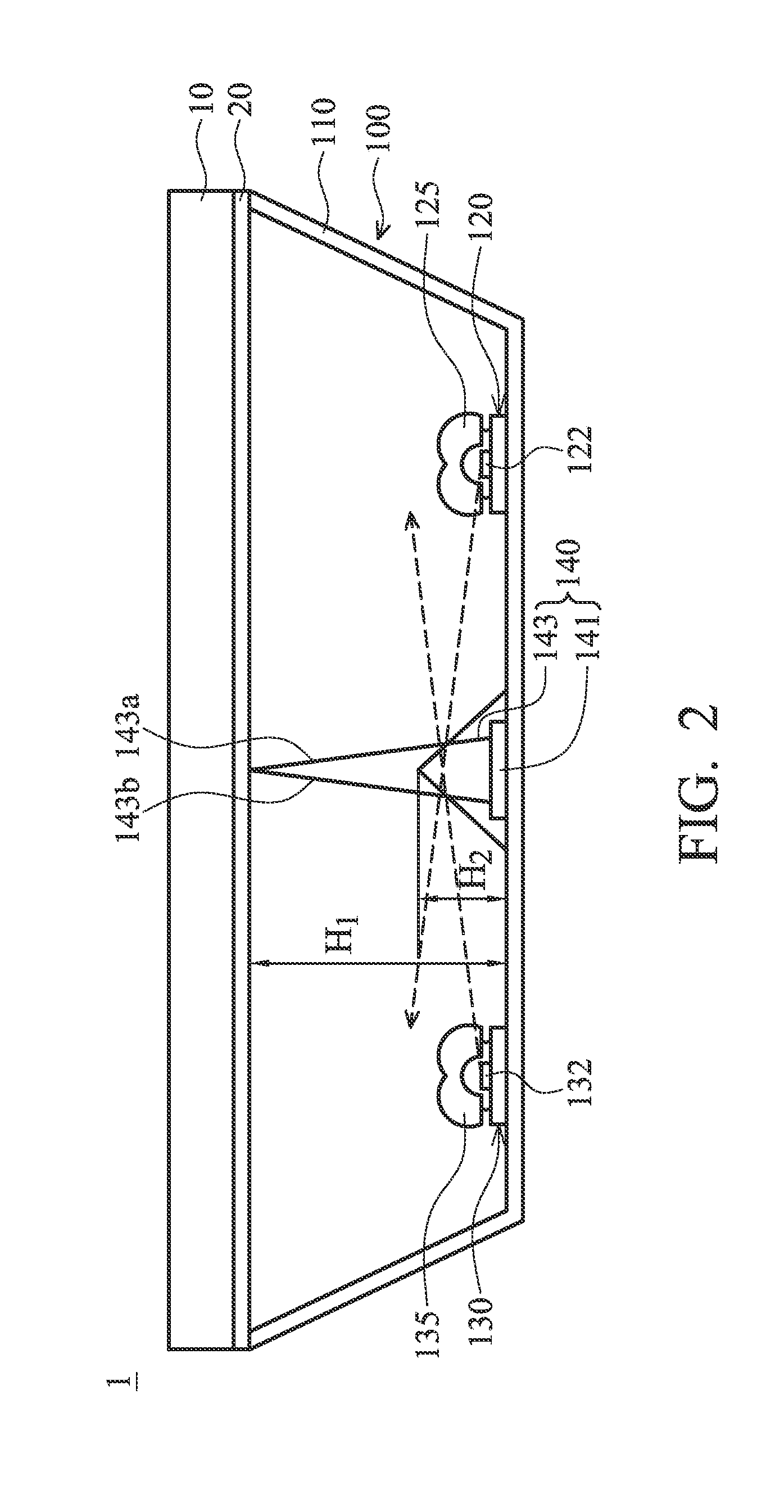
[0031]FIG. 3 shows a partial schematic view of elements of the backlight module 100 in accordance with the present disclosure, and FIG. 4 shows a cross-sectional view taken along line a-a in FIG. 3, as seen from the extending direction V. The substrate 110 includes a lower surface 115, wherein a first region 111 and a second region 113 are divided by a dividing line M. The first and second light bars 120 and 130 are respectively disposed in the first region 111 and the second region 113 of the substrate 110. The first light bar 120 includes a plurality of first light sources 122 arranged thereon, and a plurality of optical lenses 125 (FIG. 2) are disposed upon each of the light sources 122 configured to diffuse light therefrom. The second light bar 130 includes a plurality of second light sources 132 disposed thereon, and a plurality of optical lenses 135 (FIG. 2) are disposed upon each of the light sources 132 configured to diffuse light of the second light sources 132. The first l...
second embodiment
[0039]FIG. 7 shows a schematic view of partial elements of the backlight module 200 in accordance with the present disclosure, and FIG. 8 shows a cross-sectional view taken along line b-b in FIG. 7, as seen from the extending direction V. The backlight module 200 includes a substrate 210, a first light bar 220, a second light bar 230, at least one polygonal support member 240, and a plurality of partitions 250. The substrate 210 includes a lower surface 215, wherein a first region 211 and a second region 213 of the substrate 210 are divided by a dividing line M. The first and second light bars 220 and 230 are respectively disposed in the first region 211 and the second region 213 of the substrate 210. The first light bar 220 includes a first light source 222 and a second light source 224 arranged thereon, and the second light bar 230 includes a third light source 232 disposed thereon. The first light source 222, the second light source 224 and the third light source 232 may consist ...
third embodiment
[0044]FIG. 9 shows a schematic view of elements of the backlight module 300 in accordance with the present disclosure, and FIG. 10 shows a cross-sectional view taken along line c-c in FIG. 9, as seen from the extending direction V. The backlight module 300 includes a substrate 310, a first light bar 320, a second light bar 330, at least one polygonal support member 340, and a plurality of partitions 350. The substrate 310 includes a lower surface 315, wherein a first region 311 and a second region 312 of the substrate 310 are divided by a dividing line M. The first and second light bars 320 and 330 are respectively disposed in the first region 311 and the second region 312 of the substrate 310. The first light bar 320 includes a first light source 322 and a second light source 324 arranged thereon, and the second light bar 330 includes a third light source 332 and a fourth light source 334 disposed thereon. The first light source 322, the second light source 324, the third light sou...
PUM
 Abstract
Description
Claims
Application Information