Wind turbine with bearing support

Active Publication Date: 2013-08-01
VESTAS WIND SYST AS
View PDF6 Cites 0 Cited by
  • Summary
  • Abstract
  • Description
  • Claims
  • Application Information

AI Technical Summary

Benefits of technology

The present invention aims to improve the bearing system of a wind turbine generator. It aims to alleviate, mitigate or eliminate one or more of the disadvantages that previously existed. This would make the wind turbine generator more efficient and effective in generating energy.

Problems solved by technology

Some solutions tend to provide a bearing system of one or more bearings and their supports which have proven to be so heavy and / or to be provided with relatively large dimensions that installation or servicing of these bearing systems have proven to be difficult and / or quite time consuming.
Still further such solutions, where a single bearing with supporting structure may weigh around 600-1200 kilos, have proven quite costly to produce.
Some solutions tend to necessitate a very precise positioning of bearing parts relative to the supporting structure and / or tend to require costly and / or very precise manufacturing tolerances for both the bearing and the support, in order to precisely control and support the shaft and the loads acting on the shaft.
Still further and in some solutions, upon servicing a bearing, it has proven difficult and / or time consuming to exchange the bearing, i.e. to detach the bearing from its supporting structure.
In some cases this is at least partly due to corrosion.
Some solutions have proven that they were not able to withstand the loads acting on the shaft, or have at least proven that these solutions were not able to withstand the loads in a precisely controlled manner in an amount of years as initially assessed and yet some solutions have additionally or alternatively proven to be too expensive when considering their overall effectiveness.

Method used


Image

  • Wind turbine with bearing support
  • Wind turbine with bearing support
  • Wind turbine with bearing support

Examples


Embodiment Construction

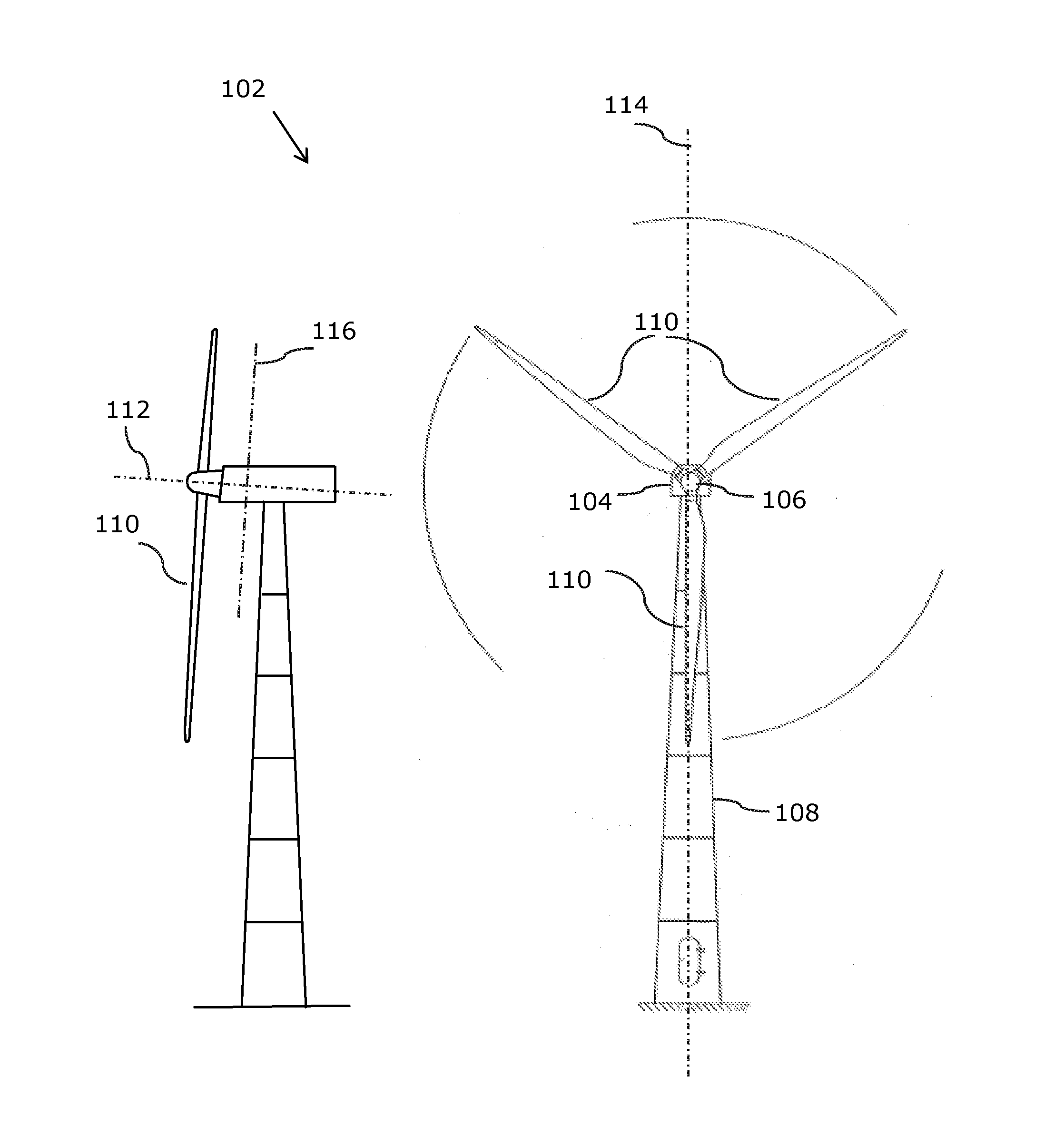
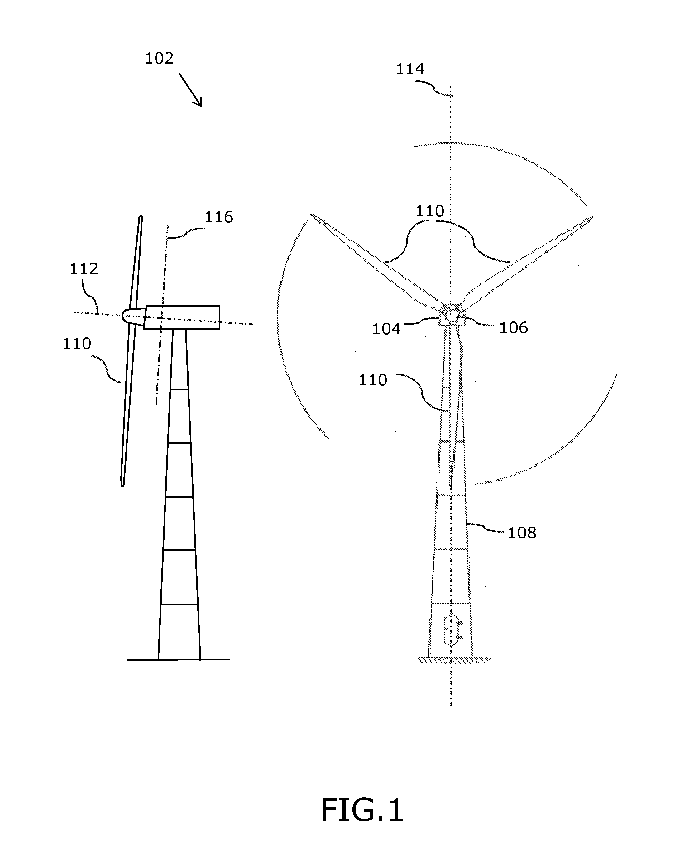
[0049]FIG. 1 shows a wind turbine generator 102 with a nacelle 104, and a rotor 106 pivotally mounted to the nacelle 104 via a shaft. The nacelle 104 is mounted on a wind turbine tower 108 via a rotary joint enabling a yawing rotation of the nacelle relatively to the tower.

[0050]The rotor 106 of the wind turbine of the present example includes three wind turbine blades 110 attached to the rotor in a root end of the blades. The rotor is fixed to a main shaft (not seen in FIG. 1, e.g. refer to FIG. 2) of the wind turbine and rotates in a precise and controlled manner with the main shaft. The main shaft has a centre axis 112. The centre axis is positioned substantially in middle or in the middle of e.g. the tower of the WTG. The length of the blades of the wind turbine in the shown example is approximately 40 meter, but blade lengths such as between 25 and 70 meters are also usual. On the figure the straight dash-dotted line illustrates a vertical plane 114.

[0051]To the left of the dra...


PUM


Abstract

In order to provide a wind turbine generator with a shaft and a bearing system which bearing system, e.g., using less material or using material which is relatively cheaper or which is not needed to have the same strength in comparison with some other solutions, there is disclosed a wind turbine generator with a bearing system including a lockable connection comprising a bearing surface and a support surface which surfaces are engaged when the lockable connection is locked and where forces from the shaft are transferred via the bearing and into the support through the bearing surface and wherein a support angle of the support surface, relatively to a shaft plane formed by rotating the shaft around a first axis, which first axis is perpendicular to the centre axis and which first axis is comprised in a vertical plane, is ranging from and including 5 degrees to and including 70 degrees.

Description

FIELD OF THE INVENTION[0001]The invention relates to a wind turbine generator with an improved bearing system, and in particular to an improved bearing system of a kind for precisely controlling and supporting a main shaft of the wind turbine.BACKGROUND OF THE INVENTION[0002]A Wind turbine generator (WTG) is used to gather wind energy and to transform the energy into another form of energy. For this purpose most wind turbine generators include a shaft which in one end is coupled to a rotor comprising a number of wind turbine blades. In the opposite end, the shaft is normally connected to a driven wind turbine part. This driven wind turbine part may be an entrance member of a gearbox or an entrance member or torque transferring member of an electric energy generator. Upon rotation of the shaft, in response to wind acting on the blades, energy can be transformed.[0003]In order to control precisely the rotation of the shaft while also supporting the shaft, the shaft is supported by a ...

Claims


Application Information

Patent Timeline
IPC IPC(8): F03D11/00
CPCF03D11/0008Y02E10/722F16C35/067F16C23/06F03D80/70F05B2240/54F05B2260/30F05B2260/301F16C2360/31Y02E10/72F16C35/04
Inventor DEMTRODER, JENS
Owner VESTAS WIND SYST AS
Why Eureka
Try Eureka