Eureka AIR delivers breakthrough ideas for toughest innovation challenges, trusted by R&D personnel around the world.

Prosthetic joint

a technology for orthopedic prosthetics and knee joints, applied in the field of total joint replacement orthopedic prosthetics, can solve the problems of insufficient extension-flexion range of most tkr implants, difficulty in replicating with a prosthesis, and insufficient technology and materials for knee articular components of prosthetic knees to provide shape-change functionality, etc., to achieve the effect of preventing posterior subluxation of the tibia

Inactive Publication Date: 2013-08-01
EPIC ORTHO
View PDF6 Cites 35 Cited by
  • Summary
  • Abstract
  • Description
  • Claims
  • Application Information

AI Technical Summary

Benefits of technology

The present invention is a joint replacement prosthesis for total joints, such as knees, that helps increase flexibility and better mimic natural movement. The prosthesis has features like uniform and equal radii of the femoral and lateral condyles, as well as gradual changes in the medial and lateral constructions of the femoral and tibial components for better internal rotation of the tibia at deep flexion angles. The femoral component has an asymmetric ridge and the tibial component has a matching groove that mates at flexion angles of approximately 60-80 degrees to prevent posterior subluxation of the tibia relative to the femur in deeper flexion positions. The asymmetric ridge also helps ridge-groove articulation at -60 degrees.

Problems solved by technology

In a natural knee, the relative movement of the femur, tibia, and patella (the knee cap) is a complex combination of flexion-extension, translation, and rotational movements in all six degrees of freedom and is difficult to emulate with a prosthesis.
However, current technology and materials for prosthetic knee articular components are not sufficiently advanced to provide shape change functionality.
Also, most TKR implants do not provide an extension-flexion range anywhere near the roughly 165° range of motion of a natural knee.

Method used


Image

  • Prosthetic joint
  • Prosthetic joint
  • Prosthetic joint

Examples


Embodiment Construction

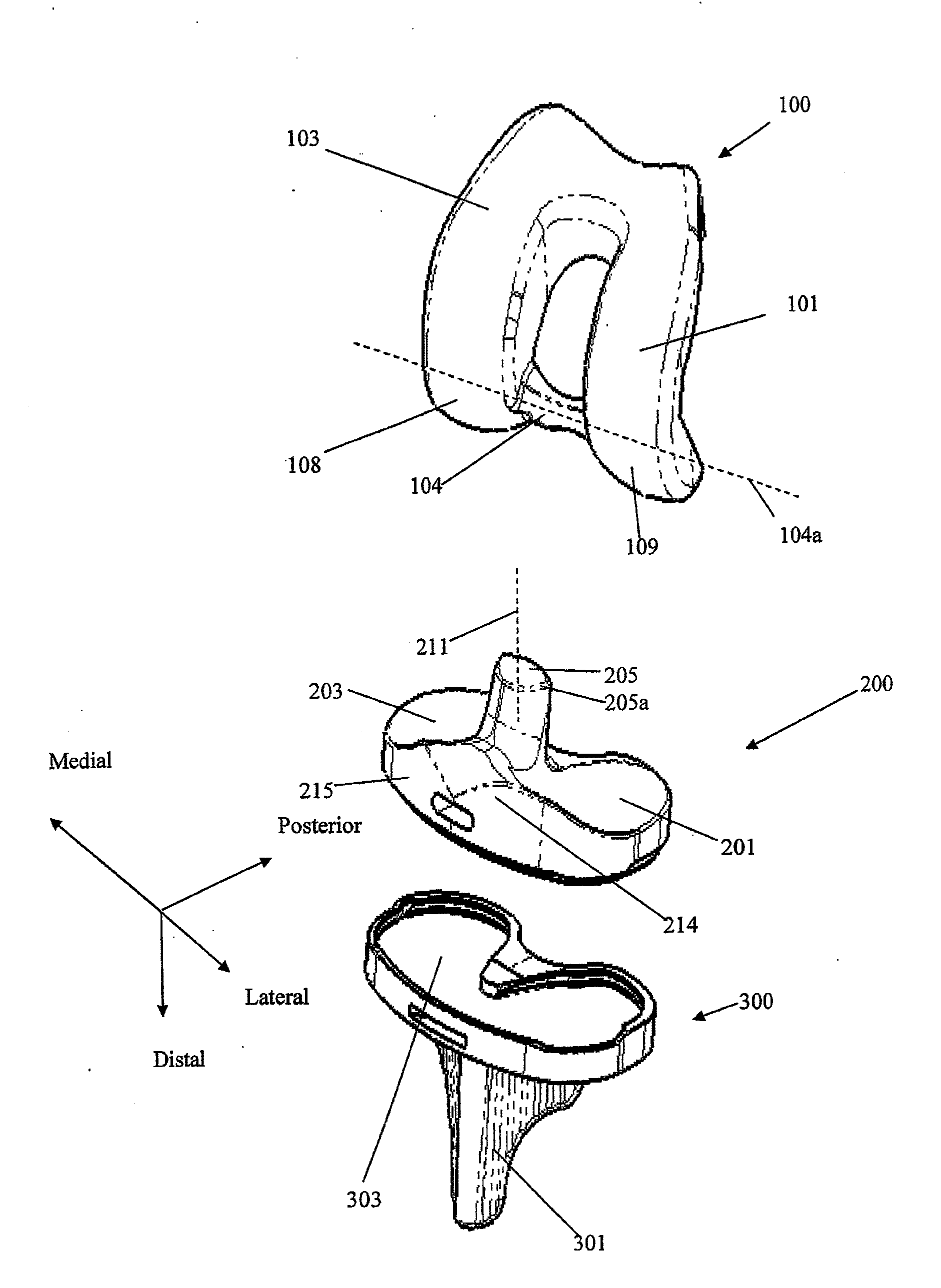
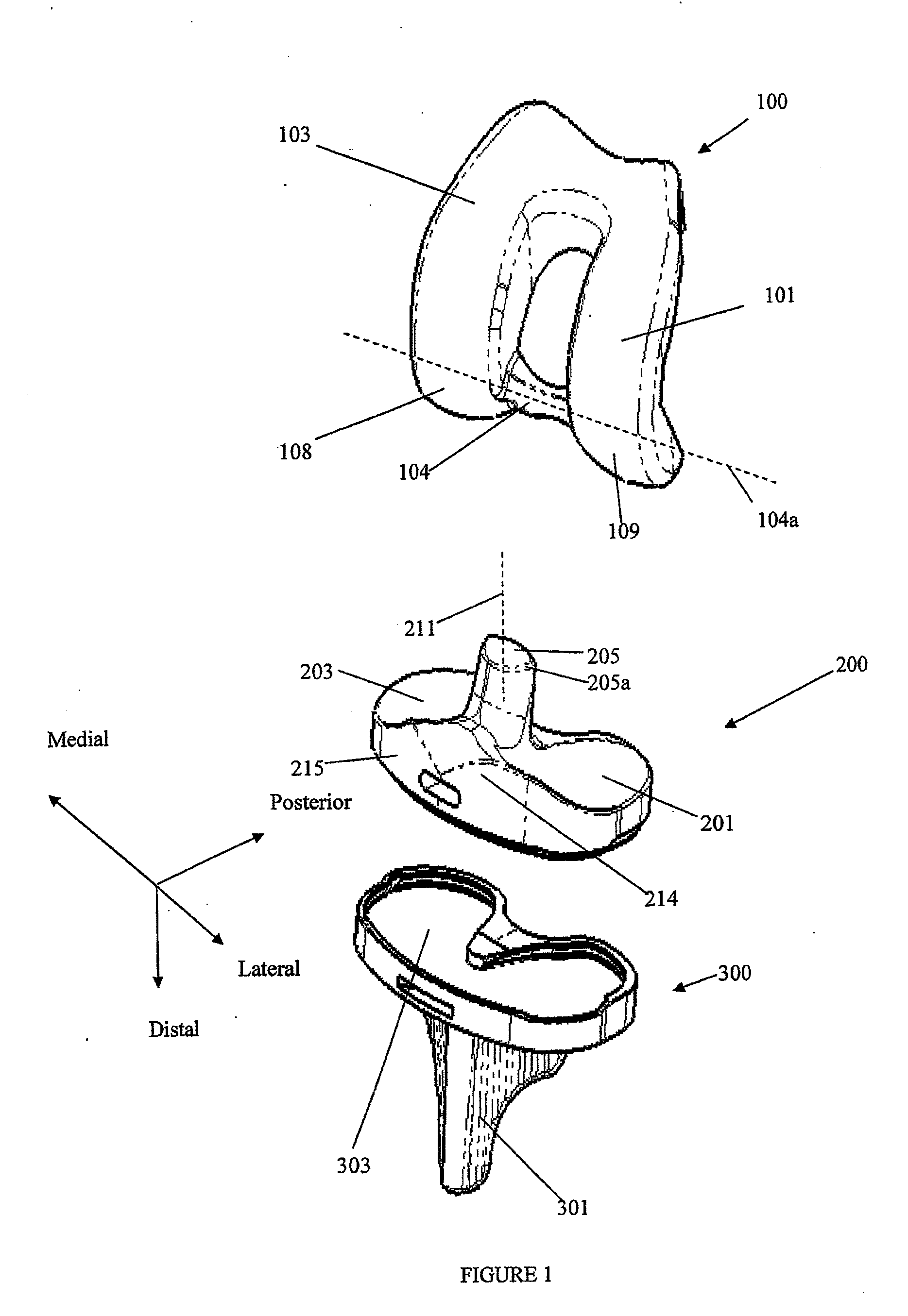
[0042]FIG. 1 is an exploded view of several of the articular components of a TKR prosthetic implant in accordance with one embodiment of the invention. The implant comprises of a femoral articular component 100, a tibial articular component 200, and a tibial stem component 300. The femoral articular component 100 is placed on a patient's distal femur after appropriate resection of the femur. In some cases, to provide better support, the femoral articular component 100 may be mounted on a femoral stem (not shown) that is implanted into an intramedullary canal drilled into the distal femur. The femoral articular component 100 may be formed of any biocompatible material that is hard, durable, and has a relatively low coefficient of friction, such as polished cobalt chromium alloys, titanium alloys, or high molecular weight polyethylene. The femoral articular component 100 essentially replaces the condyles of the natural knee and therefore comprises two condylar articular surfaces, a me...


PUM


Abstract

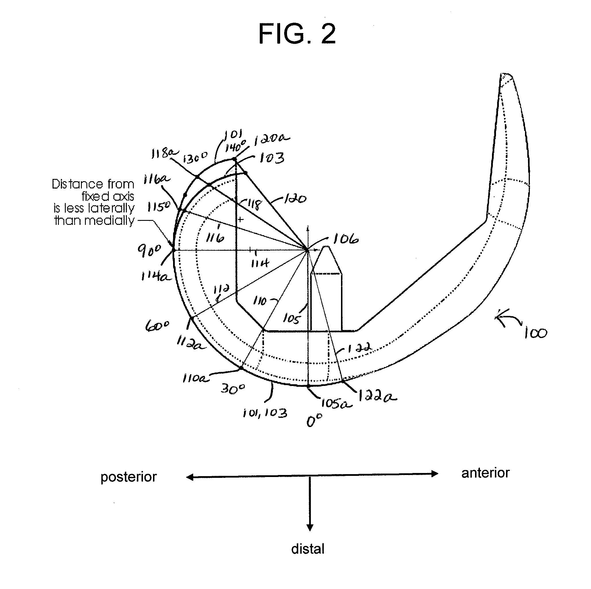
A joint prosthesis comprising, e.g., a femoral component and a tibial component. The medial and lateral condylar articular surfaces may have substantially uniform and equal radii from full extension to about 90° of flexion. From 90°, the lateral condylar articular surface has a smaller radius than the medial condylar articular surface such that the medial condyle gradually becomes increasingly more proud than the lateral condyle to facilitate internal rotation of the tibia at deep flexion. Also, the tibial articular component may include a post intermediate the medial and lateral compartments that engages a cam on the femoral articular component between the medial and the lateral condylar articular surfaces. The cam and post become congruent at flexion angles of approximately 70° flexion and mate symmetrically during the first 20°-30° of further flexion, and then mate asymmetrically at greater degrees of flexion to force internal rotation of the tibia.

Description

FIELD OF THE INVENTION[0001]The present invention relates generally to total joint replacement orthopedic prosthetics. More particularly, the invention relates to a total knee replacement (TKR) implant for use total knee arthroplasty (“TKA”).BACKGROUND OF THE INVENTION[0002]Disease and trauma affecting the articular surfaces of a joint, such as the knee joint, often are treated by surgically replacing the articular surfaces of the bones that meet at the joint, such as the femur and tibia of the knee joint, with prosthetic femoral and tibial implants, referred to as total knee replacements (“TKR”).[0003]In total knee replacement (TKR) surgery, a surgeon typically will surgically resect the distal end of the patient's femur (typically at a base angle orthogonal to the mechanical axis of the leg as measured in an A-P X-ray) and replace it with a femoral articular component.[0004]The femoral articular component may be mounted directly to the resected end of the femur or, for added stren...

Claims


Application Information

Patent Timeline
IPC IPC(8): A61F2/38
CPCA61F2/3886A61F2002/30327A61F2/3836A61F2002/30934A61F2002/30878
Inventor HAWKINS, DOUGLAS SHERMANSUSAN TRUMAN, MARI
Owner EPIC ORTHO
Why Eureka
Eureka Blog
Learn More