Operating Table with Multiple Degrees of Freedom

Active Publication Date: 2013-08-08
ZHEJIANG LINIX MOTOR
View PDF10 Cites 34 Cited by
  • Summary
  • Abstract
  • Description
  • Claims
  • Application Information

AI Technical Summary

Benefits of technology

[0020]The invention has the following advantages: the moving mechanism can drive the operating table to move on a horizontal plane and ensure the operating table can reach any location within a valid region on a horizontal plane; the moving mechanism in the X direction and the moving mechanism in the Y direction can operate separately or cooperatively, the vertical overlapping of the two moving mechanisms ensures t

Problems solved by technology

The existing operating tables generally are of fixed structures, and the locations of the operating tables are unchangeable.
However, as the pedestal of the operating table is heavy and is inconvenient to move, an empty location is required for placing the operating table again once the operating table is moved, and there should be no other objects in the empty location; meanwhile, there must be a passage for moving from the

Method used


Image

  • Operating Table with Multiple Degrees of Freedom
  • Operating Table with Multiple Degrees of Freedom
  • Operating Table with Multiple Degrees of Freedom

Examples


embodiment 1

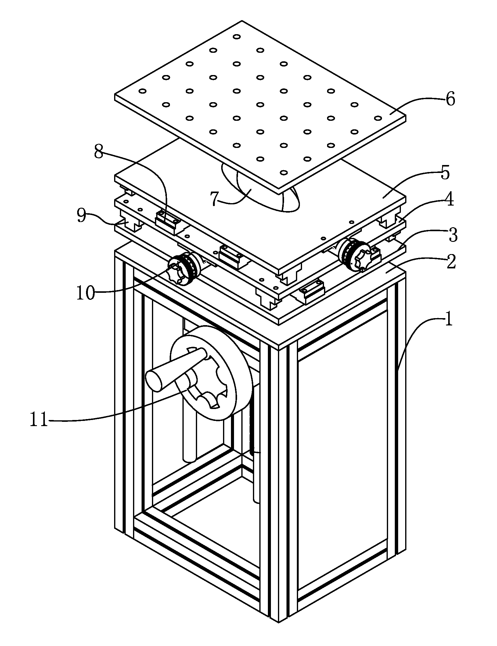
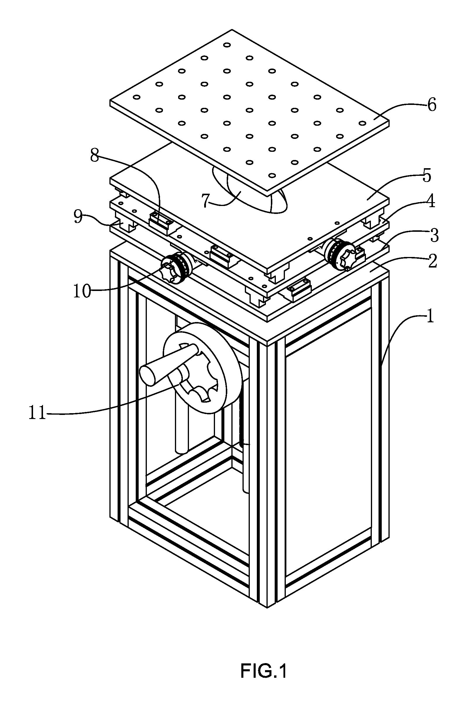
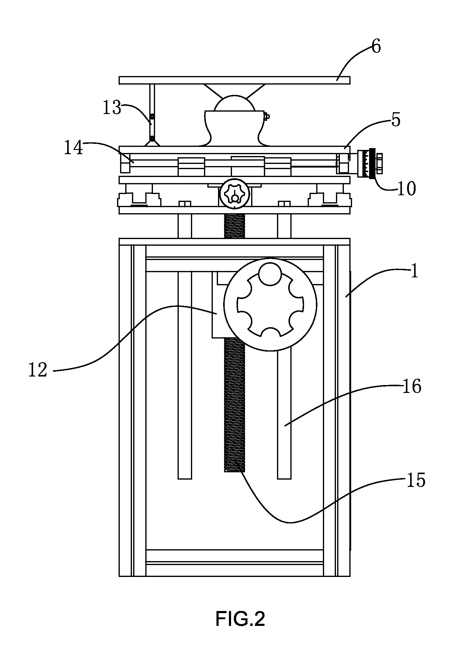
[0029]An operating table with multiple degrees of freedom (referring to FIG. 1 and FIG. 2) comprises a pedestal 1 which is of a frame structure, a moving device arranged on the pedestal, and an operating table 6 connected with the moving device. Multiple locating holes are arranged on the operating table. The pedestal is formed of multiple square steels via splicing, the upper surface of the pedestal is a supporting plate 2, the supporting plate is provided with a threaded hole and two light holes which are symmetrical with respect to the threaded hole. The moving device comprises an elevating mechanism, a moving mechanism on a horizontal plane and a multiple angle rotation mechanism. The elevating mechanism comprises a leadscrew 15 arranged vertically to the supporting plate and a rotary sleeve 12 connected with the leadscrew, the leadscrew penetrates through the rotary sleeve, a gear with gear teeth is arranged in the rotary sleeve, a threaded hole is arranged in the center part o...

embodiment 2

[0035]An operating table with multiple degrees of freedom (referring to FIG. 4 and FIG. 5) is provided. The universal joint device comprises a universal joint, the universal joint comprises a cross shaft 25 in the middle and two U-shaped forks 24 which are vertically arranged. The U-shaped forks are placed oppositely, one of the U-shaped forks is fixed with the center part of the lower surface of the operating table, and the other one is fixed with the center part of the upper surface of the moving plate in the X direction. Two vertical shaft ends of the cross shaft are provided with spline grooves, each shaft end is sleeved with a tapered locking sleeve 23 (referring to FIG. 6), the inner hole of the locking sleeve is provided with a convex rib 27 which is corresponding to the spline groove, the outer surface of the locking sleeve is a tapered surface, the end part of the U-shaped fork which is corresponding to the shaft end is provided with a tapered hole 26, the outer side of the...


PUM


Abstract

Disclosed is an operating table with multiple degrees of freedom which is capable of moving and rotating in various directions. The operating table comprises an elevating mechanism, a moving mechanism on a horizontal plane and a multiple angle rotation mechanism, with the elevating mechanism and the moving mechanism adopting a leadscrew structure, the multiple angle rotation mechanism comprising a universal joint device (7) and a locking mechanism. The moving mechanism can drive the operating table (6) to move on a horizontal plane and ensure the operating table (6) can reach any location within a valid region on a horizontal plane, the moving mechanisms in the X and Y directions can operate separately as well as cooperatively, and the multiple angle rotation mechanism drives the surface of the operating table to tilt. These mechanisms work in combination to accomplish the location change of the operating table.

Description

TECHNICAL FIELD OF THE INVENTION[0001]The invention relates to an operating table structure, and in particular to an operating table with multiple degrees of freedom, which is capable of moving and rotating in various directions.BACKGROUND OF THE INVENTION[0002]Operating tables, even some specialized operating tables, have to be configured for general machining operations. A good and suitable operating table plays a very important role in promoting the operation, thus improving the machining efficiency and improving the operation precision and stability, and also reducing the labor load of the operators. Operating tables relatively satisfy the ergonomics.[0003]The existing operating tables generally are of fixed structures, and the locations of the operating tables are unchangeable. The whole pedestal of an operating table needs to be moved to change the location of the operating table, and the location of the operating table is changed by changing the location of the pedestal. Howe...

Claims


Application Information

Patent Timeline
IPC IPC(8): B25H1/02
CPCB25H1/02B25H1/14B23Q1/626B23Q1/4857B23Q1/25
Inventor SUN, ZHUBIN
Owner ZHEJIANG LINIX MOTOR
Why Eureka
Try Eureka