
Method for object rotating by utilizing coordinate axis ratio and difference

Inactive Publication Date: 2013-08-08
HANNSTAR DISPLAY CORPORATION
View PDF7 Cites 0 Cited by
  • Summary
  • Abstract
  • Description
  • Claims
  • Application Information

AI Technical Summary

Benefits of technology

The present invention provides a method for object rotating using coordinate axis ratio and difference as a principle objective to simplify determining a computation processing required for object rotating, thereby improving the overall performance. The method prevents computation error by right-rotating the object when the axle center point and the rotation point are simultaneously located at the Y-coordinate axis and the X-coordinate value is 0. The method has the advantage of simplifying the determination steps of a computation program to reduce calculation loading and increase the efficiency of controlling object rotating.

Problems solved by technology

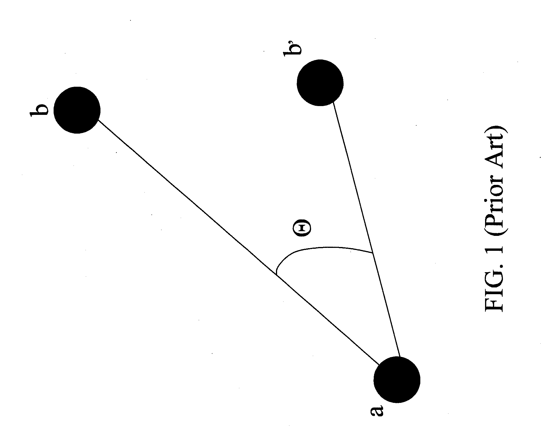
However, the microprocessor in the touch system needs more computation processing to calculate Φ angles, thereby influencing the whole performance.

Method used


Image

  • Method for object rotating by utilizing coordinate axis ratio and difference
  • Method for object rotating by utilizing coordinate axis ratio and difference
  • Method for object rotating by utilizing coordinate axis ratio and difference

Examples


Embodiment Construction

[0022]The foregoing and other technical characteristics of the present invention will become apparent with the detailed description of the preferred embodiments and the illustration of the related drawings.

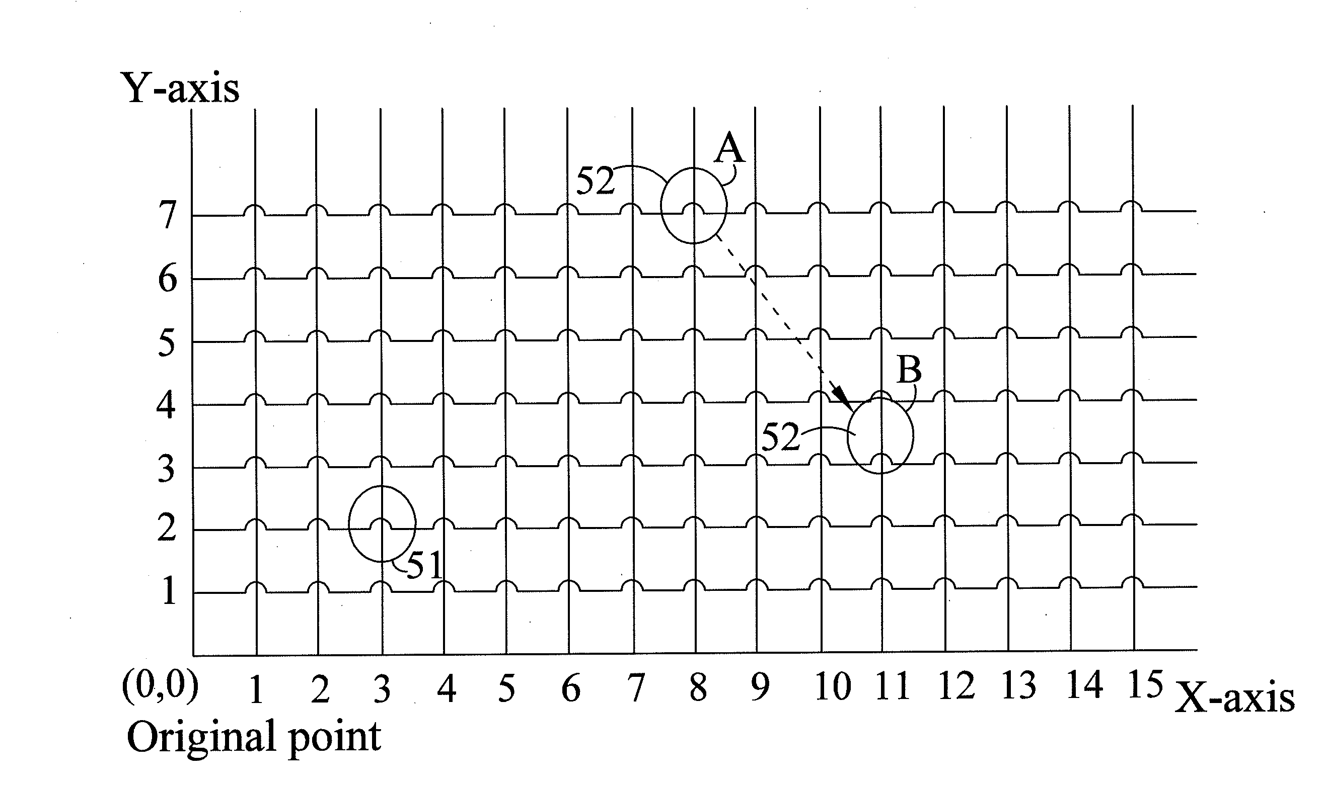
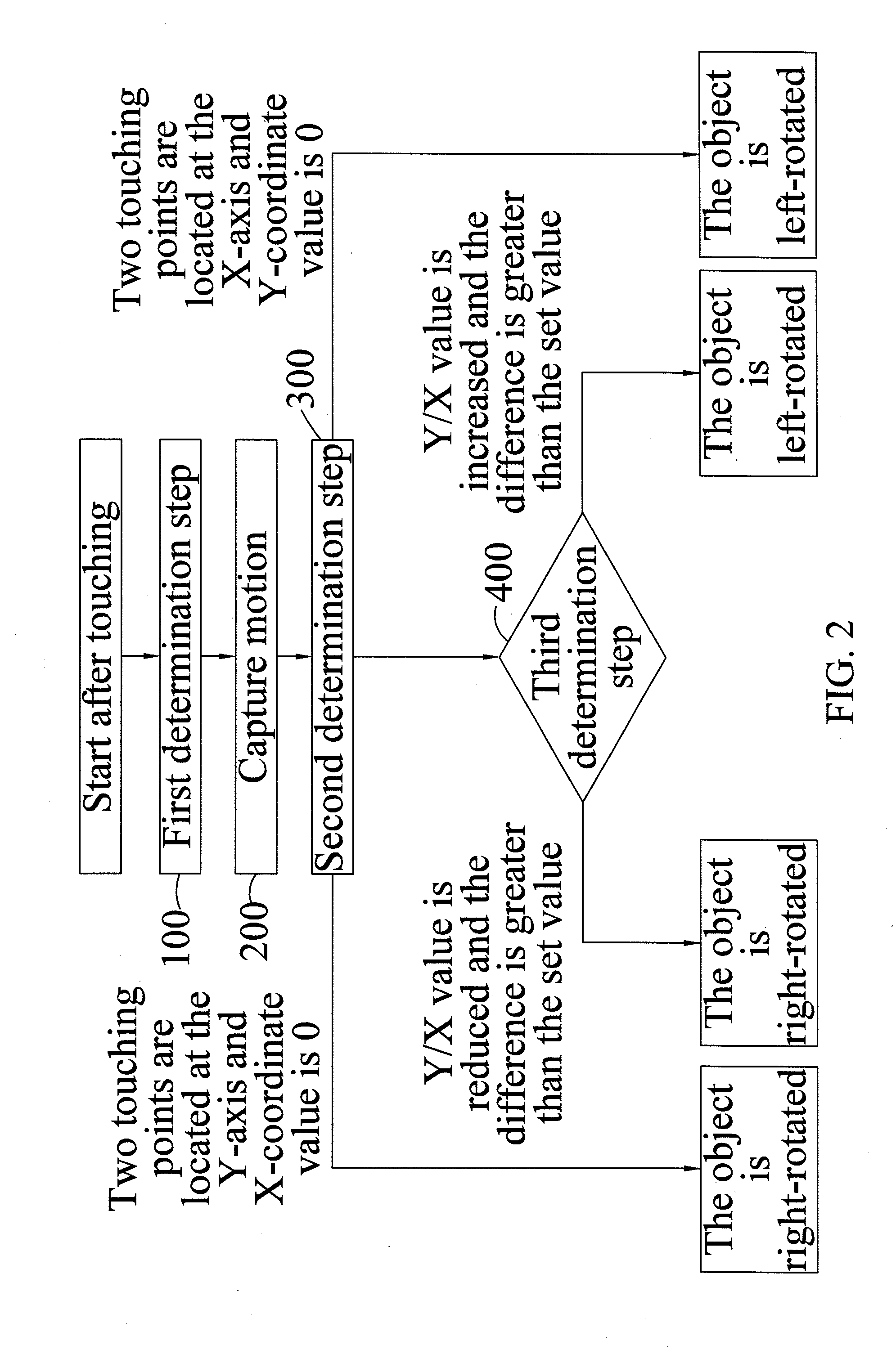
[0023]With reference to FIG. 2 to FIG. 7, FIG. 2 is a flowchart of a method for object rotating by utilizing coordinate axis ratio and difference according to the invention. FIG. 3 is a first schematic diagram of a method for object rotating by utilizing coordinate axis ratio and difference according to the invention. FIG. 4 is a second schematic diagram of a method for object rotating by utilizing coordinate axis ratio and difference according to the invention. FIG. 5 is a third schematic diagram of a method for object rotating by utilizing coordinate axis ratio and difference according to the invention. FIG. 6 is a fourth schematic diagram of a method for object rotating by utilizing coordinate axis ratio and difference according to the invention. FIG. 7 is a fifth schematic dia...


PUM


Abstract

A method of display rotation by using axis ratio and difference is disclosed. The method includes: performing a first determination step to determine whether or not two touching points exist within an object shown in a screen by using a touch algorithm; if yes, capturing X-coordinate values and Y-coordinate values of the two touching points on an X-axis and a Y-axis respectively; performing a second determination step to determine the touching point with smaller Y-coordinate value as an axle center point and the another touching point with bigger Y-coordinate value as a rotation point; performing a third determination step after the rotation point shifts to rotate object leftward or rightward by using the modulus of the variation of the ratio of the Y-coordinate value to the X-coordinate value of the rotation point and whether the axle center point and the rotation point are located on the X-axis or Y-axis.

Description

CROSS-REFERENCE TO RELATED APPLICATION[0001]This application claims the benefit of China Patent Application No. 201210024623.3, filed on Feb. 3, 2012, in the State Intellectual Property Office of the People's Republic of China, the disclosure of which is incorporated herein in its entirety by reference.BACKGROUND OF THE INVENTION[0002]1. Field of the Invention[0003]The present invention relates to a method for object rotating, and more particularly to a method for object rotating by utilizing coordinate axis ratio and difference determination.[0004]2. Description of the Related Art[0005]Current smart phones are continuously developed to provide more functions and services to satisfy our diversity of demands. Plus user-friendly, overall demands on smart phones are continuously increased to produce more solution means.[0006]Since most displays of smart phones are rectangles, many functions, such as electronic map, satellite positioning navigation, games and the like, need to perform o...

Claims


Application Information

Patent Timeline
IPC IPC(8): G06F3/041
CPCG06F3/04883G06F3/0416
Inventor LEE, MENG-JU
Owner HANNSTAR DISPLAY CORPORATION
Learn More