Engine control system, vehicle system, and engine control method
- Summary
- Abstract
- Description
- Claims
- Application Information
AI Technical Summary
Benefits of technology
Problems solved by technology
Method used
Image
Examples
first embodiment
[0023]Hereinafter, an engine control system according to a first embodiment will be described in detail referring to FIGS. 1 to 4.
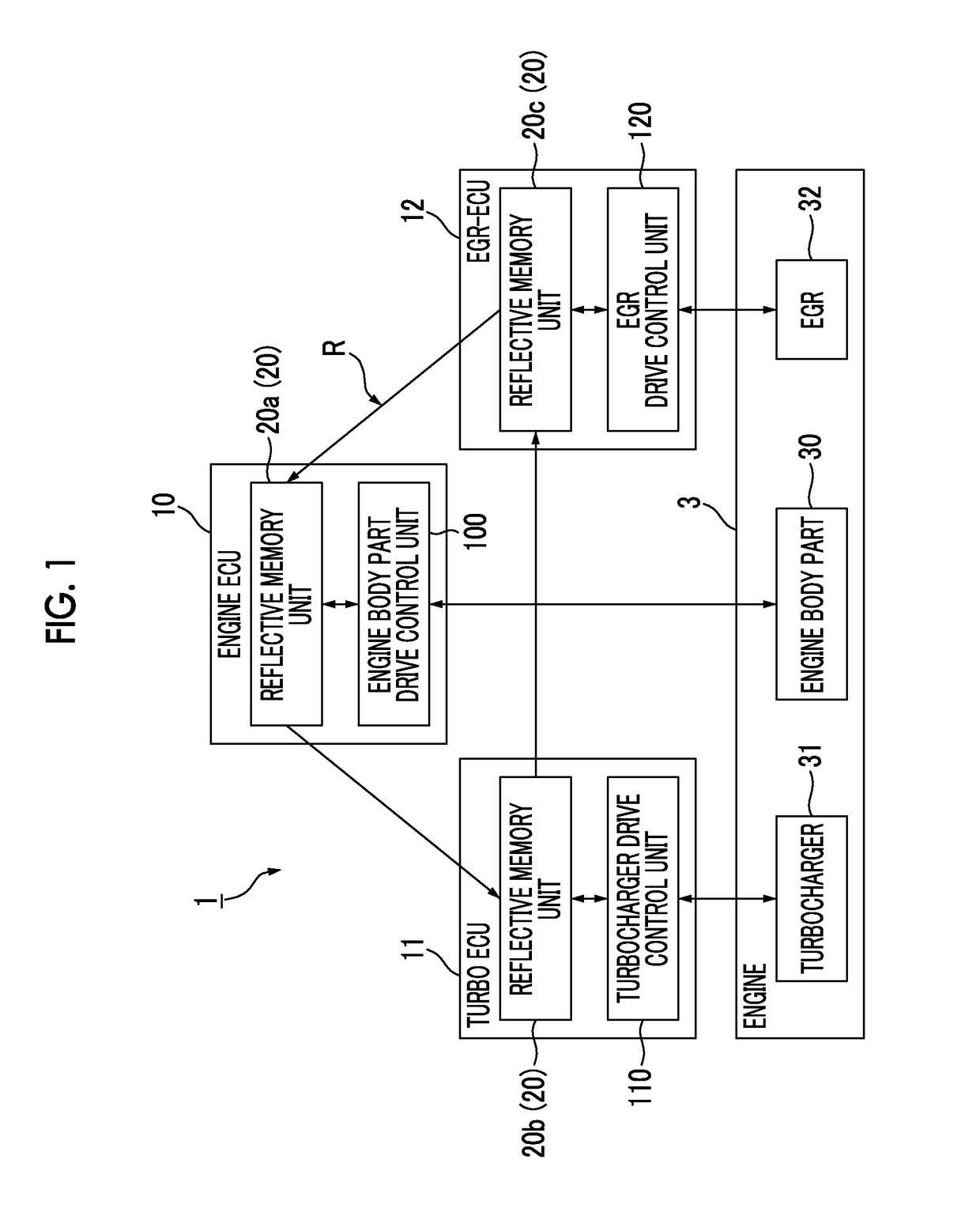
[0024]FIG. 1 is a diagram showing the functional configuration of the engine control system according to the first embodiment.
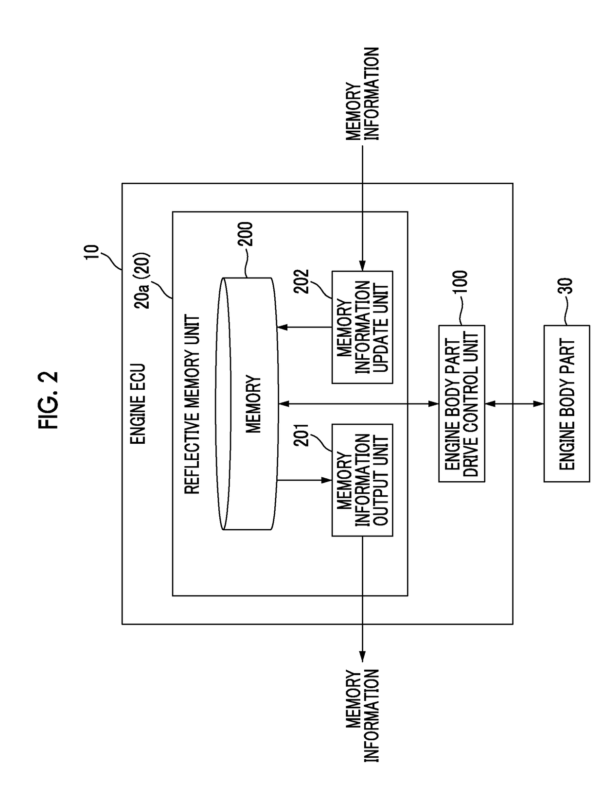
[0025]As shown in FIG. 1, an engine control system 1 includes a plurality of control devices (engine ECU 10, turbo ECU 11, and EGR-ECU 12) which respectively have a plurality of engine units (engine body part 30, turbocharger 31, and EGR 32) constituting an engine 3 as a target to be controlled.
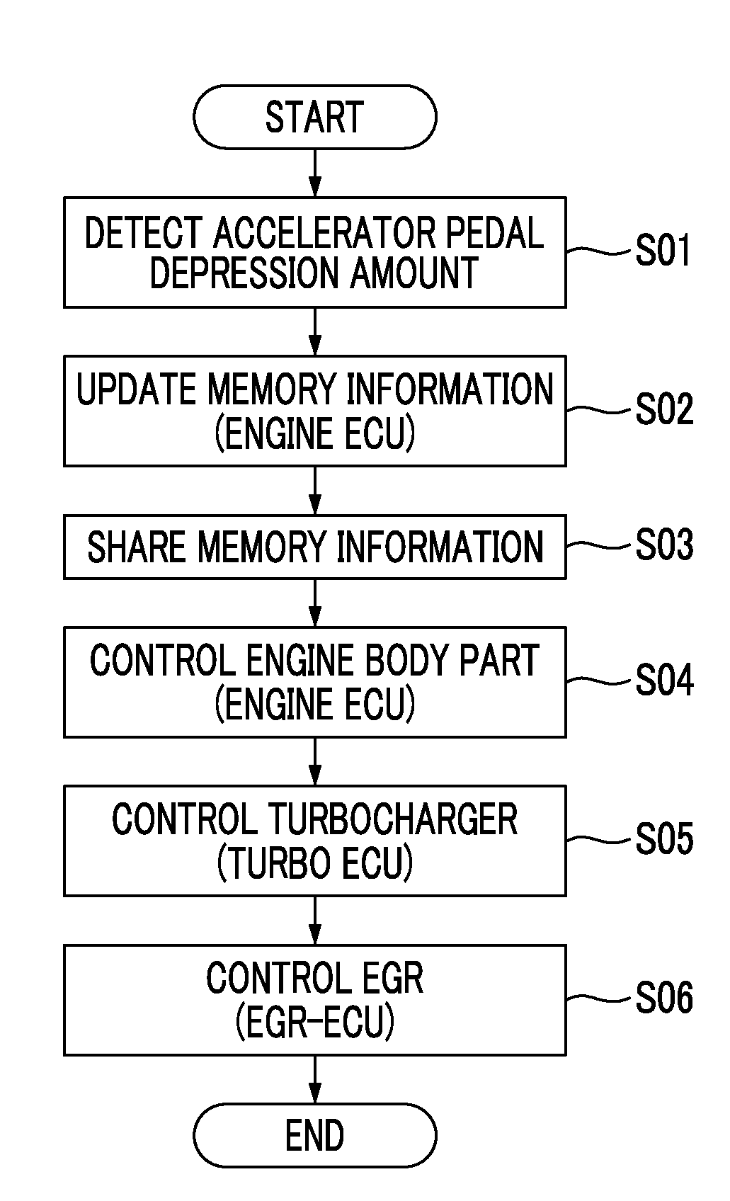
[0026]The engine ECU 10 is a control device which controls the drive of an engine body part 30 in the engine 3. The engine ECU 10 performs control such that the operation state of the entire engine 3 is optimized in cooperation with the turbo ECU 11 and the EGR-ECU 12 according to an input command based on a driver's operation (depression of an accelerator pedal, or the like). The cooperative operation of the turbo ECU 11 and the EGR-ECU 12 ...
second embodiment
[0072]Next, an engine control system according to a second embodiment will be described in detail referring to FIG. 5.
[0073]FIG. 5 is a diagram illustrating the function of the engine control system according to the second embodiment.
[0074]As in the first embodiment, each of the drive control units (an engine body part drive control unit 100, a turbocharger drive control unit 110, and an EGR drive control unit 120) according to this embodiment controls the drive of the engine unit as a target to be controlled of each drive control unit based on various command values stored in the reflective memory unit 20 (memory 200) in each control device.
[0075]Each of the drive control units according to this embodiment shares various observation values corresponding to the respective command values through the reflective memory unit 20. Each drive control unit controls the drive of each engine unit to be controlled with reference to a storage area, into which information relating to the drive o...
third embodiment
[0085]Next, a vehicle system according to a third embodiment will be described in detail referring to FIG. 6.
[0086]FIG. 6 is a diagram showing the functional configuration of the vehicle system according to the third embodiment.
[0087]As shown in FIG. 6, a vehicle system 5 includes the engine control system 1 according to the first embodiment (or the second embodiment), a bus 50, a body control system 51, and an information system 52.
[0088]As described above, the engine control system 1 has a plurality of control devices (the engine ECU 10, the turbo ECU 11, and the EGR-ECU 12) which respectively control the respective engine units constituting the engine 3.
[0089]The body control system 51 is one in-vehicle system mounted in a vehicle, and is an in-vehicle system which controls windows, doors, or the like of the vehicle.
[0090]Similarly, the information system 52 is one in-vehicle system mounted in the vehicle, and is an in-vehicle system which controls a car navigation device, audio ...
PUM
 Abstract
Description
Claims
Application Information
 - R&D
- Intellectual Property
- Life Sciences
- Materials
- Tech Scout
- Unparalleled Data Quality
- Higher Quality Content
- 60% Fewer Hallucinations
Browse by: Latest US Patents, China's latest patents, Technical Efficacy Thesaurus, Application Domain, Technology Topic, Popular Technical Reports.
© 2025 PatSnap. All rights reserved.Legal|Privacy policy|Modern Slavery Act Transparency Statement|Sitemap|About US| Contact US: help@patsnap.com


