Eureka AIR delivers breakthrough ideas for toughest innovation challenges, trusted by R&D personnel around the world.

Sensor fault detection method, motor drive system, and electric power steering system

Inactive Publication Date: 2019-09-05
NIDEC CORP
View PDF0 Cites 2 Cited by
  • Summary
  • Abstract
  • Description
  • Claims
  • Application Information

AI Technical Summary

Benefits of technology

This patent describes a new way to detect sensor faults in a computer system that reduces the amount of computing needed. This method can be used in a motor drive system that uses the sensor fault detection.

Problems solved by technology

If one of these sensors fails, the motor drive system malfunctions, and consequently the motor drive system cannot recover in many instances.

Method used


Image

  • Sensor fault detection method, motor drive system, and electric power steering system
  • Sensor fault detection method, motor drive system, and electric power steering system
  • Sensor fault detection method, motor drive system, and electric power steering system

Examples


first embodiment

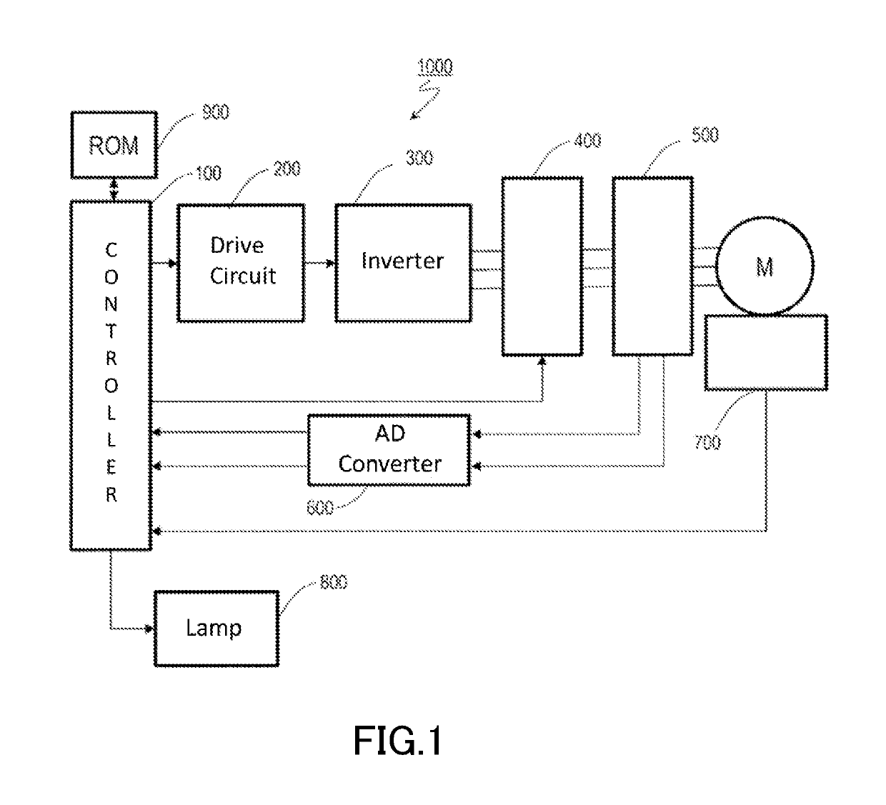
[0042]FIG. 1 schematically illustrates hardware blocks of a motor drive system 1000 employing sensor fault detection according to a

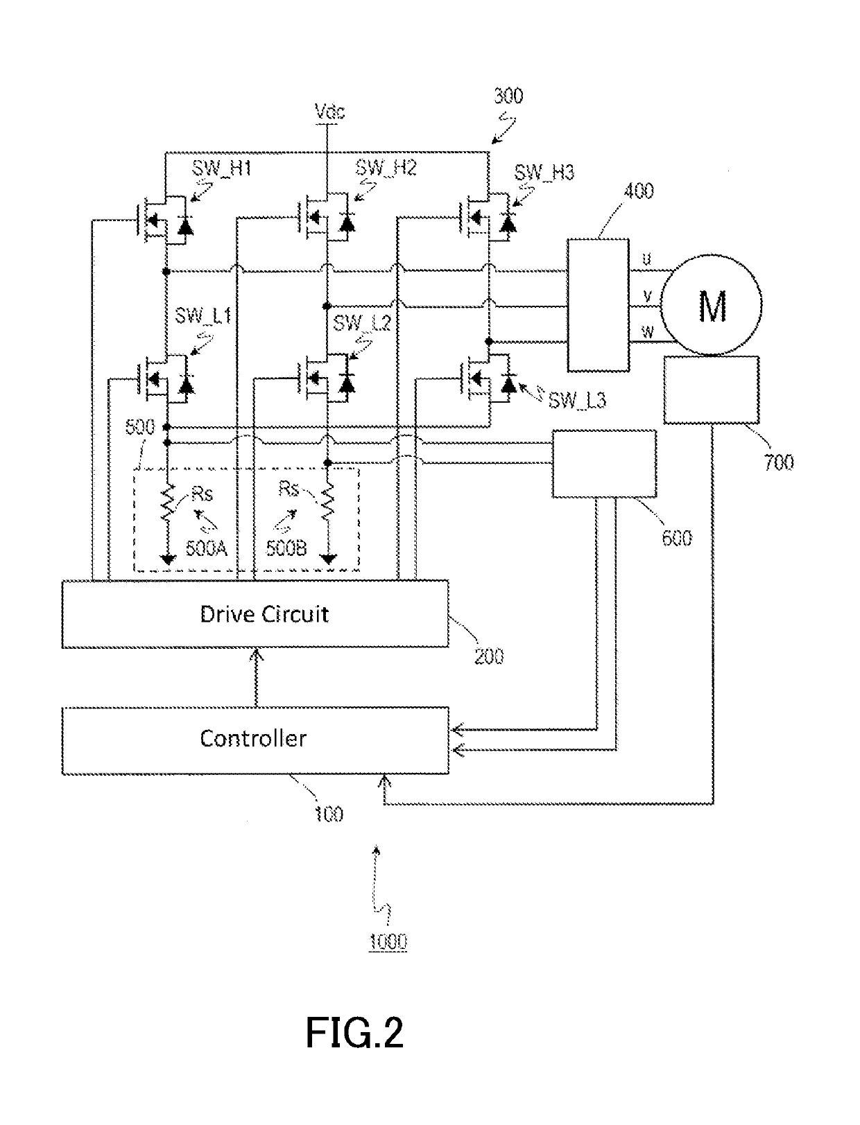
[0043]The motor drive system 1000 typically includes a motor M, a controller 100, a drive circuit 200, an inverter (also referred to as an “inverter circuit”) 300, a shutdown circuit 400, a plurality of current sensors 500, an analog-to-digital conversion circuit (hereinafter, referred to as an “AD converter”) 600, an angle sensor 700, a lamp 800, and a read only memory (ROM) 900. For example, the motor drive system 1000 may be designed in modules as a power pack, and may be manufactured and sold in the form of a motor module including a motor, a sensor, a driver, and a controller. It should be noted herein that the motor drive system 1000 will be described as an exemplary system including as its constituent the motor M. Alternatively, the motor drive system 1000 may be a system excluding as its constituent the motor M, the system being configured to dri...

second embodiment

[0137]With reference to FIGS. 31 and 32, a description will be given of a method for detecting a sensor fault according to a

[0138]In the first embodiment, the counter electromotive force error Ver is represented by the function of the error between the estimated phase angle ρs and the measured phase angle ρ. Equation (6) described above is changed in accordance with a procedure to be described below, which makes it possible to understand the physical meaning of the counter electromotive force error Ver.

[0139]FIG. 31 illustrates a relationship between the composite magnetic flux Ψs and the estimated phase angle ρs.

[0140]First, Equation (8) is obtained by replacing p in Equation (6) with ρ′. In Equation (8), a relation of ρ′=90°−ρ is satisfied.

Ver=BEMFβ·cos ρ′−BEMFα·sin ρ′  Equation (8)

[0141]Equation (9) is obtained by dividing both the sides of Equation (8) by the absolute value BEMF.

Ver / BEMF=(BEMFβ / BEMF)·cos ρ′−(BEMFα / BEMF)·sin ρ′  Equation (9)

[0142]The composite magnetic flux Ψs is...

third embodiment

[0150]FIG. 33 schematically illustrates a typical configuration of an EPS system 2000 according to a

[0151]Typically, a vehicle such as an automobile is equipped with an EPS system. The EPS system 2000 according to the third embodiment includes a steering system 520, and an assist torque mechanism 540 that generates an assist torque. The EPS system 2000 generates an assist torque that assists a steering torque in a steering system, the steering torque being generated when a driver turns a steering wheel. The assist torque reduces a burden of a steering operation on the driver.

[0152]For example, the steering system 520 may include a steering wheel 521, a steering shaft 522, universal joints 523A and 523B, a rotating shaft 524, a rack and pinion mechanism 525, a rack shaft 526, left and right ball joints 552A and 552B, tie rods 527A and 527B, knuckles 528A and 528B, and left and right wheels 529A and 529B.

[0153]For example, the assist torque mechanism 540 includes a steering torque sen...


PUM


Abstract

A sensor fault detection method for detecting a fault of at least one sensor in a motor drive system includes performing a calculation (A) to determine a counter electromotive force error Ver relative to an αβ fixed coordinate system or a dq rotating coordinate system. The calculation (A) is performed based on currents Iα and Iβ on αβ axes in the αβ fixed coordinate system, reference voltages Vα* and Vβ* on the αβ axes, and an electrical angle θe of a rotor. The counter electromotive force error Ver represents a function of an error between an estimated phase angle ρs and a measured phase angle ρ based on sensor values to be measured by the sensors. The method also includes detecting the fault based on the counter electromotive force error Ver.

Description

BACKGROUND OF THE INVENTION1. Field of the Invention[0001]The present disclosure relates to a sensor fault detection method for use in a motor drive system, a motor drive system, and an electric power steering system.2. Description of the Related Art[0002]Recently, an electric drive system has been widely used for various applications. A non-limiting example of the electric drive system is a motor drive system. For example, the motor drive system controls an electric motor (hereinafter, referred to as a “motor”) by vector control. Some current sensors and angle sensors have been utilized in the vector control. If one of these sensors fails, the motor drive system malfunctions, and consequently the motor drive system cannot recover in many instances. Therefore, there have been actively proposed various methods for detecting a sensor fault in a motor drive system.[0003]According to the related art described above, a computer bears a large load of calculation for sensor fault detection...

Claims


Application Information

Patent Timeline
IPC IPC(8): H02P21/13H02P21/18H02P21/22H02P21/36B62D5/04
CPCH02P21/13H02P21/18B62D5/0484H02P21/36B62D5/049H02P21/22H02P27/06H02P21/06H02P6/182H02P29/0241
Inventor GHADERI, AHMAD
Owner NIDEC CORP
Why Eureka
Eureka Blog
Learn More