Method for controlling external control type fan coupling device

Inactive Publication Date: 2009-11-12
USUI KOKUSAI SANGYO KAISHA LTD
View PDF10 Cites 2 Cited by
  • Summary
  • Abstract
  • Description
  • Claims
  • Application Information

AI Technical Summary

Benefits of technology

[0023]According to the present invention, since arithmetic processing of a quick acceleration detection signal can be carried out in a short cycle, it becomes possible to instantaneously control the torque transmission from the drive side to the driven side of the external control type fan coupling device so as to be minimized when detecting quick start or quick acceleration of a vehicle. Therefore, it is possible to attempt to reduce fan noise in quick start or quick acceleration of a vehicle, to reduce the loss in horsepower, and to carry out favorable acceleration of the vehicle. In addition, according to the present invention, since arithmetic processing of signals other than the quick acceleration detection signal is carried out in a long cycle, the calculation load in the ECU can be reduced, and the memory can be downsized, wherein it becomes possible to prevent heat from being generated from the CPU.

Problems solved by technology

However, any one of the Patent Documents described above do not disclose that the frequency of arithmetic processing for speed control of fan rotation is set to a different value, depending on the type of sensor output signal.
Accordingly, this results in a lowering in the acceleration capacity due to horsepower being taken by the driven side of the fan coupling device and generation of large noise in the fan.
And, where a high rotation speed state of the fan is sustained in response to a high opening degree of the accelerator after quick start or quick acceleration, not only is large noise sustained from such a fan, but also a great loss in horsepower is brought about, wherein fuel efficiency is lowered.
In addition, with the calculation load in the ECU increased, there is a fear that arithmetic processing for other control by the ECU is delayed or heat generation from the CPU is increased.

Method used


Image

  • Method for controlling external control type fan coupling device
  • Method for controlling external control type fan coupling device
  • Method for controlling external control type fan coupling device

Examples


Embodiment Construction

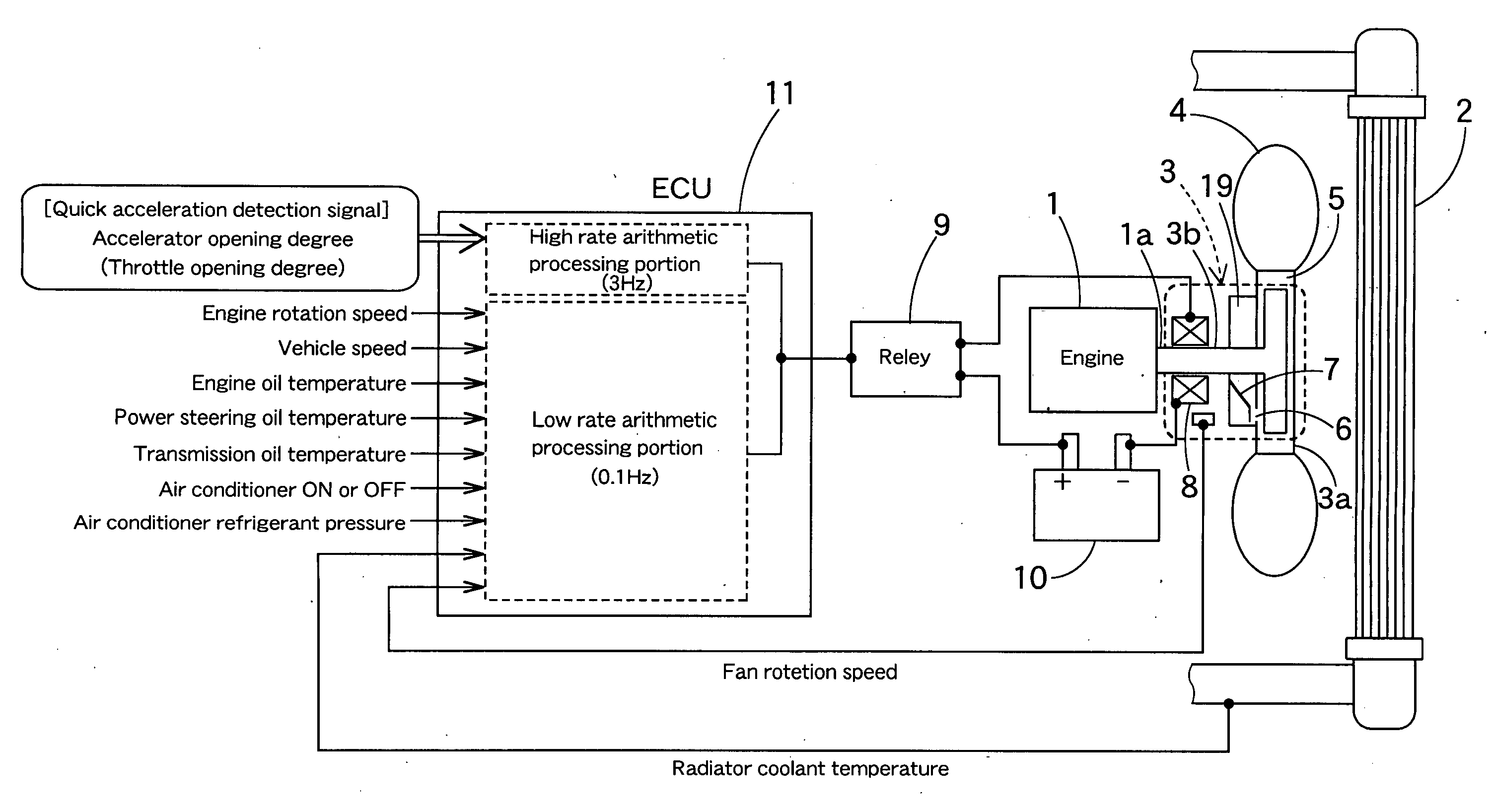
[0041]Hereinafter, a description will be given of embodiments of the present invention based on the drawings. Since respective embodiments described below relate to a method for controlling an external control type fan coupling device of a vehicle that carries out acceleration using an accelerator pedal, an accelerator opening degree signal is used as a quick acceleration detection signal.

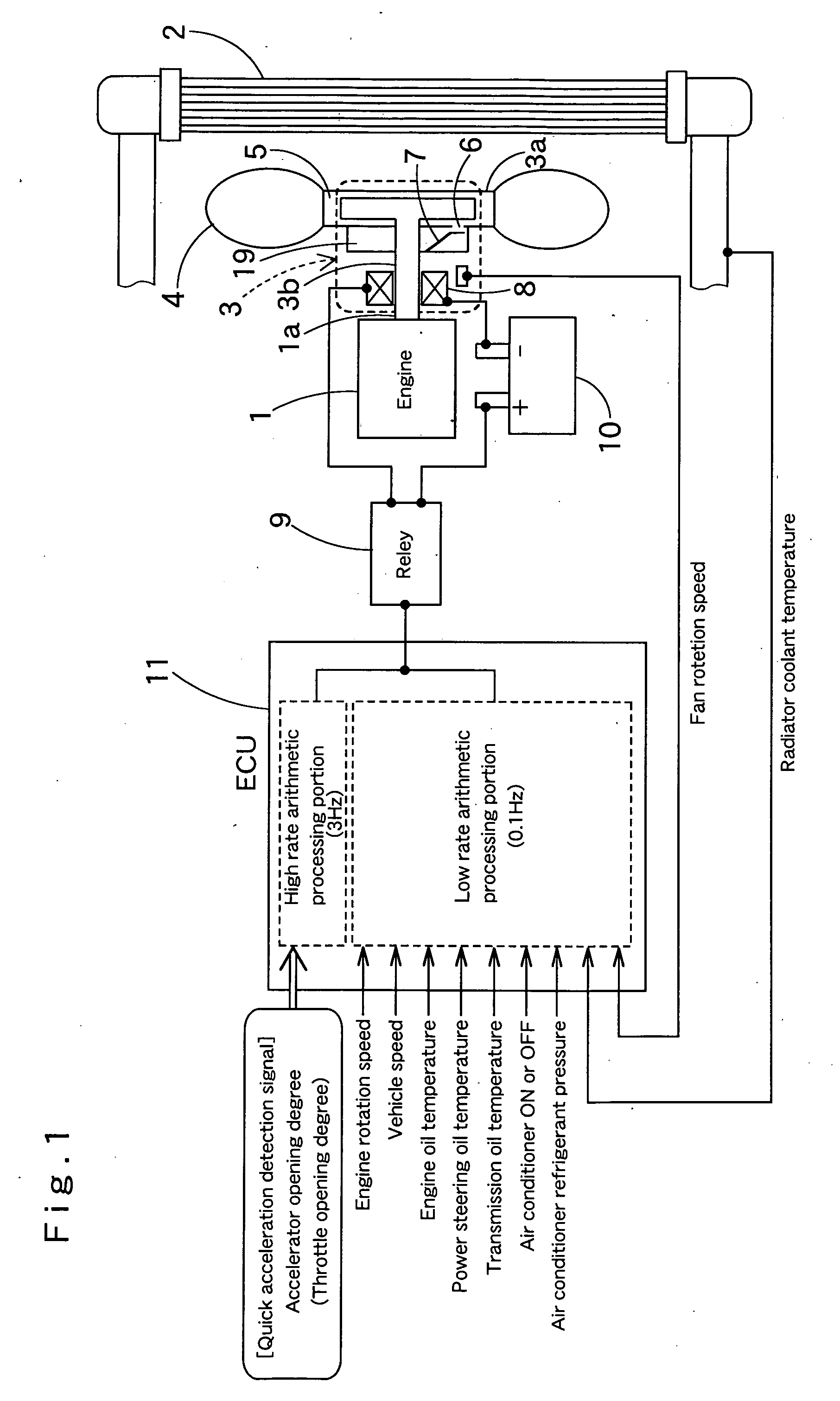
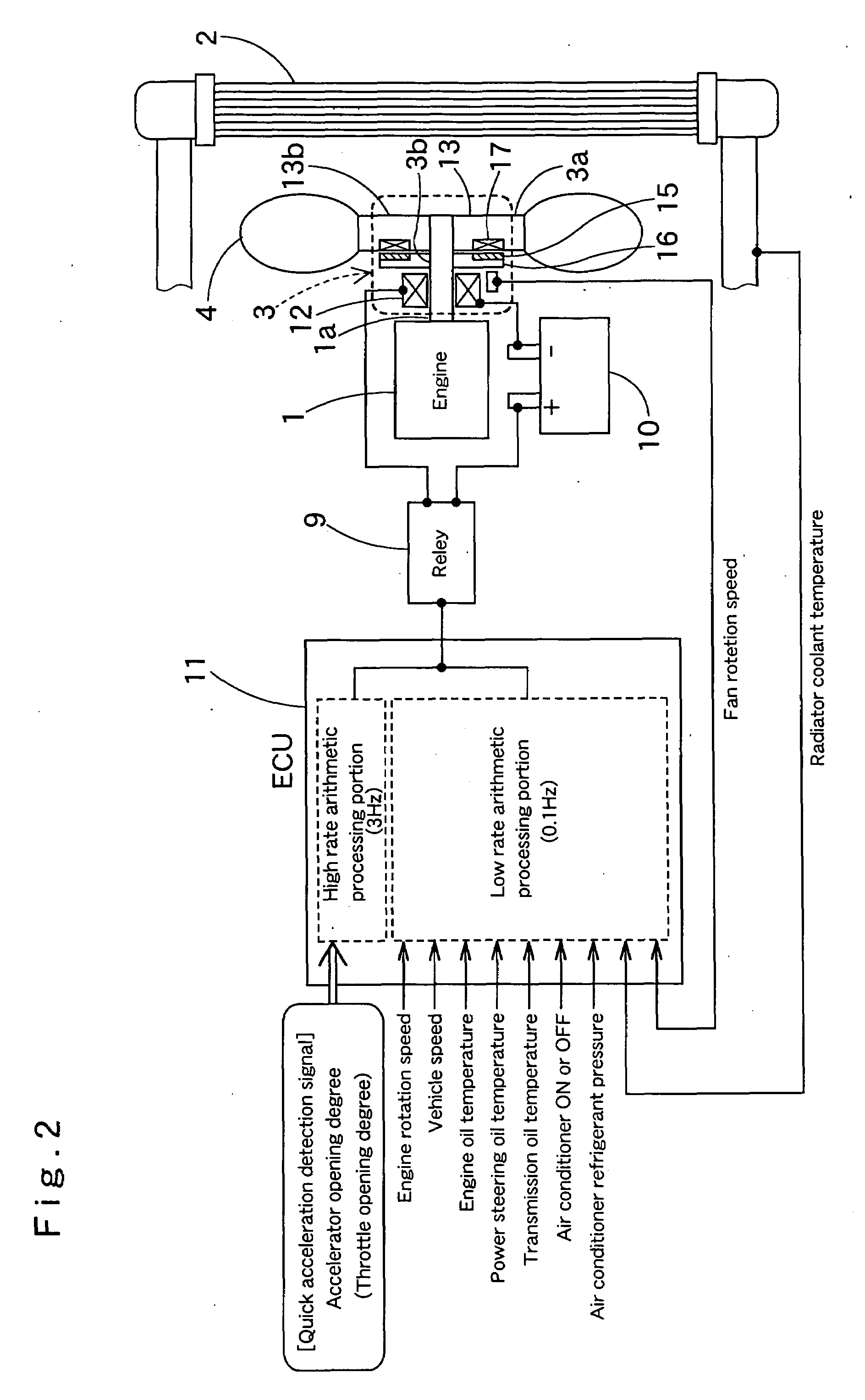
[0042]FIG. 1 is a configuration diagram of a system for carrying out a method for controlling an external control type fan coupling device according to one embodiment of the present invention, FIG. 2 is a configuration diagram of another system for carrying out the same controlling method, and FIG. 3 is a configuration diagram of still another system for carrying out the same controlling method.

[0043]First, a description will be given of an embodiment according to FIG. 1. In FIG. 1, reference numeral 1 denotes an internal combustion engine of a vehicle, and 2 denotes a radiator in which an engine c...


PUM


Abstract

In a method for controlling an external control type fan coupling device 3, arithmetic processing to determine the rotation speed of fan 4 with a quick acceleration detection signal used as a parameter is carried out at a high frequency than that in arithmetic processing to determine the rotation speed of fan 4 using signals other than the quick acceleration detection signal as a parameter.

Description

TECHNICAL FIELD[0001]The present invention relates to a method for controlling an external control type fan coupling device, in detail, to a method for controlling an external control type fan coupling device, which controls an external control type fan coupling device disposed between a fan drive output shaft side of an internal combustion engine and a fan based on various types of signals such as an accelerator opening signal, in order to control the rotation speed of an internal combustion engine cooling fan in a vehicle such as an automobile, etc.BACKGROUND ART[0002]Conventionally, an external control type fan coupling device has been disclosed, which consists of a combination of an electromagnet and a fluid coupling, a combination of an electromagnetic clutch and a magnet type coupling, or a combination of an electric actuator and a fluid coupling, and a method for controlling a rotation speed of a fan has been disclosed, which uses a control system such as PID control (feedbac...

Claims


Application Information

Patent Timeline
IPC IPC(8): F16D35/02F16D31/00
CPCF01P7/08F01P7/084F01P7/085F16D48/08F16D2500/1022F16D2500/10418F01P2025/66F16D2500/50293F16D2500/7044F01P2025/40F01P2025/50F01P2025/60F01P2025/64F16D2500/3109F16D35/02
Inventor TAKIKAWA, KAZUNORI
Owner USUI KOKUSAI SANGYO KAISHA LTD
Why Eureka
Try Eureka