

Fastening structure for thermal module
- Summary
- Abstract
- Description
- Claims
- Application Information
AI Technical Summary
Benefits of technology
Problems solved by technology
Method used
Image

Examples
first embodiment
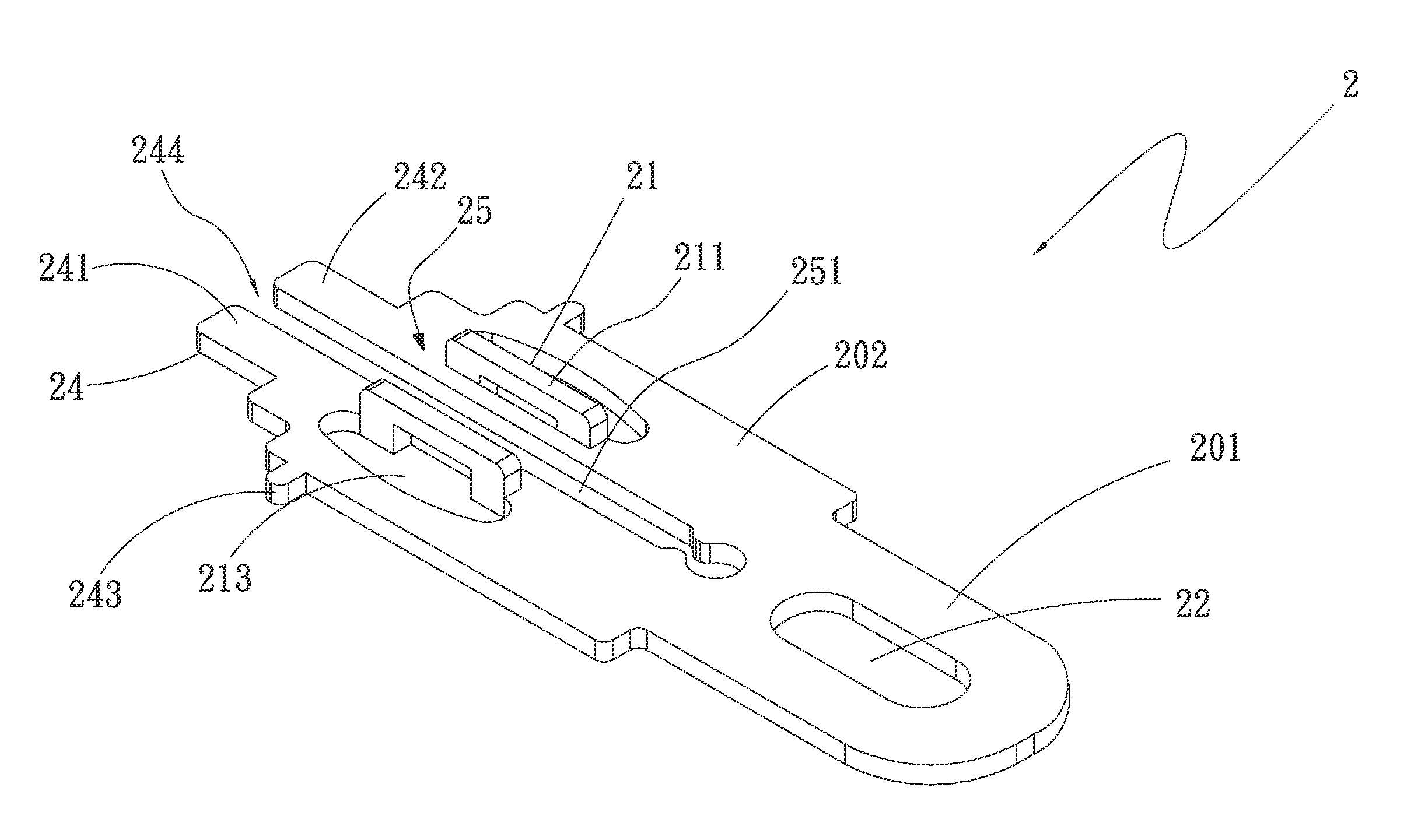
[0034]The elastic press portion 21 is formed on the main body 2 between the insertion unit 24 and the fastening portion 22. The elastic press portion 21 includes at least one elastic press arm 211 and at least one opening 213. In the illustrated first embodiment, the elastic press arms 211 are provided on one side of the second body section 202 to face each other. The openings 213 are respectively located between one elastic press arm 211 and one corresponding lateral side of the second body section 202 to penetrate the second body section 202 in a thickness direction thereof, so that a user may conveniently apply forces on the elastic press arms 211.
[0035]As shown in FIG. 2, a flexible space 25 is defined between the elastic press portion 21 and the main body 2, so that the facing elastic press arms 211 on the second body section 202 are movable in the flexible space 25. In the flexible space 25, an axial long slot 251 is further formed on the second body section 202 between the fa...
second embodiment
[0039]In the event it is necessary to rework, simply push the elastic press arms 211 toward the central area of the flexible space 25 at the same time, and the first and second insertion sections 241, 242 as well as the second body section 202 will elastically deform and move toward the central area of the space 244 and of the long slot 251, respectively. Meanwhile, the stop sections 243 will also move along with the second body section 202 to thereby separate from the passage defined between two adjacent radiating fins 311. At this point, the main body 2 can be quickly detached from the recess 313 on the radiating fins 311 without causing damage to the main body 2 and the heat radiating unit 31. Therefore, the fastening structure for thermal module according to the present invention provides high convenience and flexibility in use and enables easy reworking when necessary.
[0040]Further, since the main body 2 of the fastening structure is connected to the heat radiating unit 31 with...
third embodiment
[0042]Further, in the third embodiment, the stop sections 243 of the insertion unit 24 are located on the first and second insertion sections 241, 242. That is, as can be seen in FIG. 4B, the stop sections 243 are separately projected from the first and the second insertion section 241, 242 toward a central area of the receiving space 245.
[0043]When the facing elastic press arms 211 are subjected to two outward push forces to shift away from the flexible space 25, the first and the second insertion section 241, 242 are brought to elastically deform and shift away from the receiving space 245. Meanwhile, the second body section 202 will also elastically deform to move away from the long slot 251.
[0044]On the other hand, when the applied outward push forces are removed, the facing elastic press arms 211 and the first and second insertion sections 241, 242 would simultaneously spring back to a state free of any pressure. With the above design, the fastening structure of the present inv...
PUM
 Abstract
Description
Claims
Application Information