Gas sensor

a gas sensor and sensor technology, applied in the field of gas sensors, can solve the problem that the combustion products cannot accumulate any more, and achieve the effects of reducing the response time for the detection of combustible gases, improving the gas exchange rate, and improving the sensitivity of the gas sensor

Active Publication Date: 2013-08-08
DRAGER SAFETY
View PDF0 Cites 3 Cited by
  • Summary
  • Abstract
  • Description
  • Claims
  • Application Information

AI Technical Summary

Benefits of technology

[0005]An object of the present invention is to improve a gas sensor of the type mentioned in the introduction such that the response time for the detection of the combustible gases is shortened and the sensitivity of the gas sensor is increased by a better gas exchange Furthermore, the effect of combustion products on the diffusion of the combustible gas towards the sensor element shall be reduced or prevented altogether.

Problems solved by technology

In addition, possible combustion products are removed by the gas flow from the interior of the housing, so that combustion products cannot accumulate any more.

Method used


Image

  • Gas sensor
  • Gas sensor
  • Gas sensor

Examples


Embodiment Construction

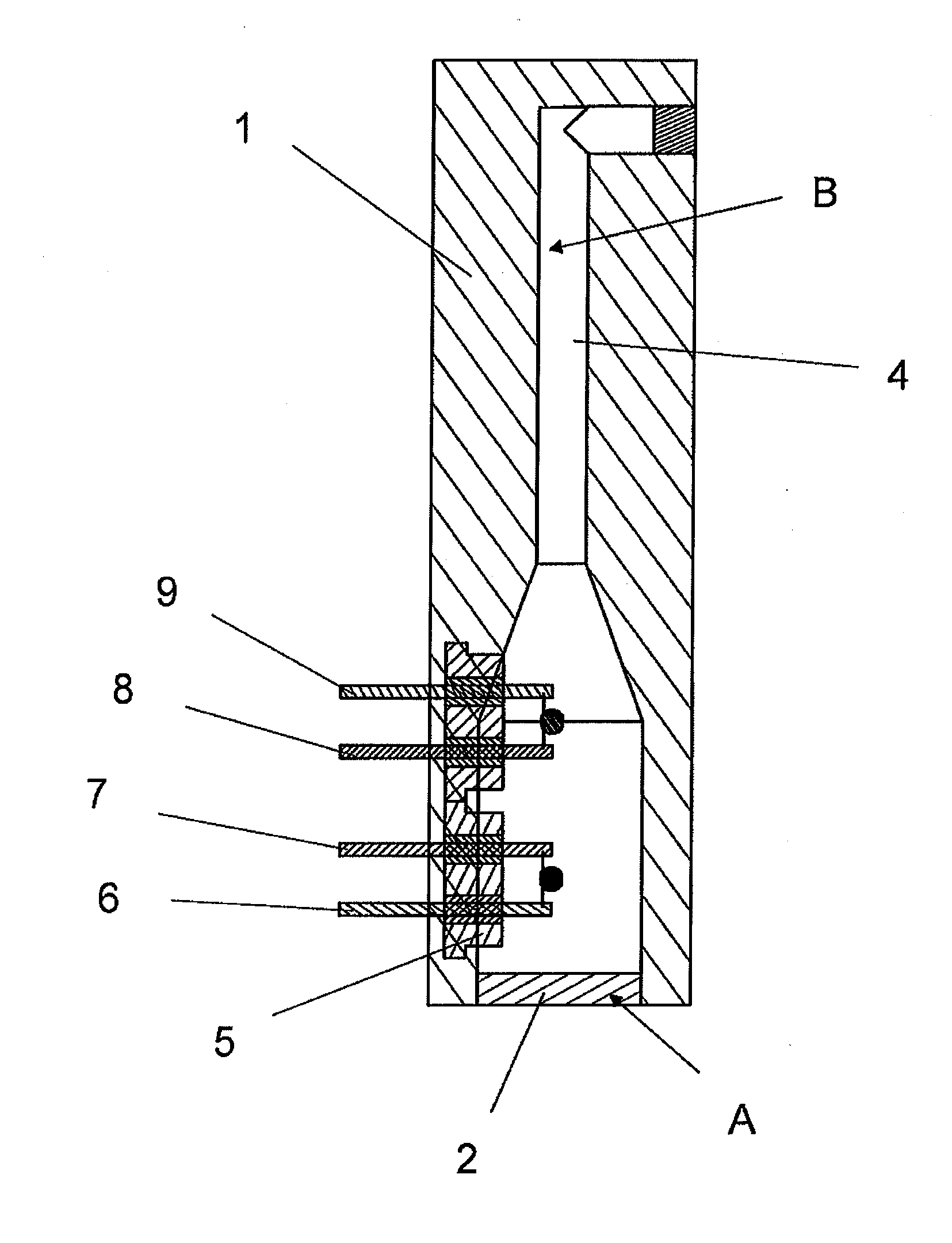
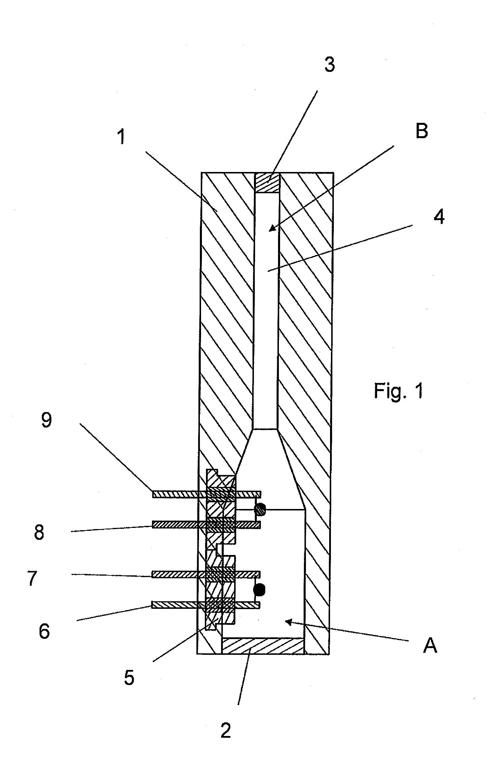
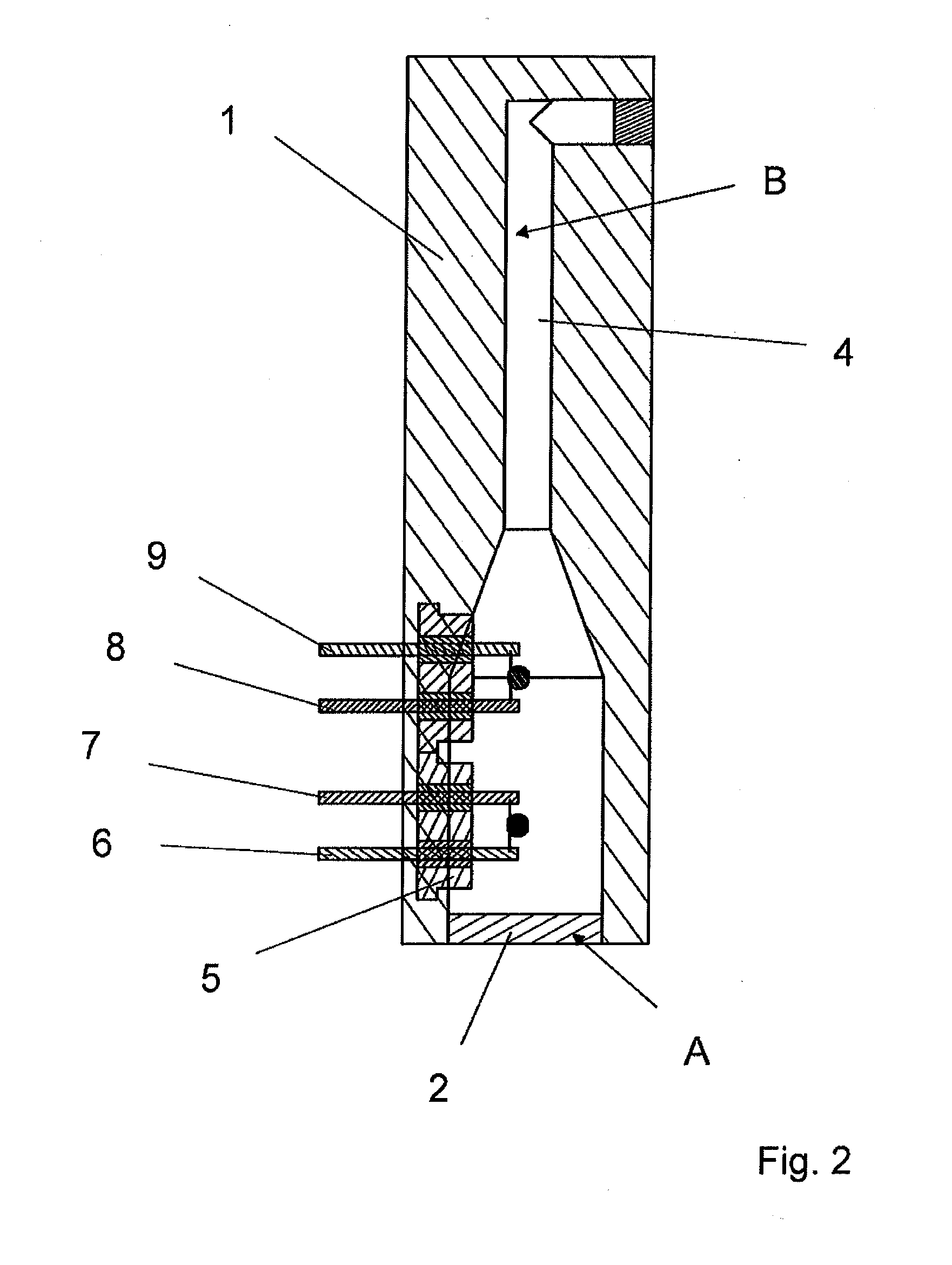
[0021]Referring to the drawings in particular, FIG. 1 shows a cross-sectional view of a gas sensor. The gas sensor has a housing 1 and a gas-permeable inlet opening 2 located at the bottom at the housing. A gas flow channel 4 extends from gas inlet opening 2 to a gas-permeable outlet opening 3 at the top at housing 1. Flow channel 4 has, following gas inlet opening 2, a first cylindrical section A with a first diameter, which is joined by a second cylindrical section B with a smaller diameter, which leads to the gas-permeable outlet opening 3. A first sensor element and a second sensor element are arranged in lower section A of flow channel 4, one sensor element being in contact with the atmosphere in the flow channel and the other sensor element not having any contact with the atmosphere in the flow channel, for which purpose one of the sensor elements is enclosed with a capsule (not shown). The second sensor element is thus used as a reference. The first sensor element is provided...


PUM

PropertyMeasurementUnit
lengthaaaaaaaaaa
operating temperatureaaaaaaaaaa
diameteraaaaaaaaaa

Abstract

A gas sensor for detecting combustible gases is provided with a catalytic sensor element. The catalytic sensor element is arranged in a housing (1) surrounding the catalytic sensor element on all sides. The housing has a gas-permeable inlet opening. The gas sensor has electric lines, which are in connection with the sensor element and have terminals located outside of the housing (1). The housing has a gas-permeable inlet opening (2) and a gas-permeable outlet opening (3) and a flow channel (4) connecting the gas-permeable inlet opening (2) and the gas-permeable outlet opening (3). The sensor element is arranged in the flow channel

Description

CROSS REFERENCE TO RELATED APPLICATIONS[0001]This application claims the benefit of priority under 35 U.S.C. §119 of German Patent Application DE 10 2012 002 456.8 filed Feb. 8, 2012, the entire contents of which are incorporated herein by reference.FIELD OF THE INVENTION[0002]The present invention pertains to a gas sensor for detecting combustible gases with a catalytic sensor element, which is heated during operation and is arranged in a housing enclosing it on all sides, which has a gas-permeable inlet opening, and with electric lines, which are in connection with the sensor element and have terminals located outside the housing.BACKGROUND OF THE INVENTION[0003]Such a gas sensor is known, for example, from DE 10 2005 020 131 B3 (corresponding to U.S. Pat. No. 7,426,849). Such gas sensors operate with catalytic oxidation of combustible gases, which leads to a rise in temperature at the sensor element, which in turn entails a change in the resistance of the sensor element, which ca...

Claims


Application Information

Patent Timeline
Patent Type & Authority Applications(United States)
IPC IPC(8): G01N25/32
CPCG01N25/32
Inventor UNGER, JURGENSCHLICHTE, MLADEN
Owner DRAGER SAFETY
Why Eureka
Try Eureka