
Controlling a motor of an injection device

a technology of injection device and control motor, which is applied in the direction of flow monitors, intravenous devices, other medical devices, etc., can solve the problems of unoptimized energy efficiency and achieve the effect of reliable signal

Active Publication Date: 2013-08-08
SANOFI AVENTIS DEUT GMBH
View PDF2 Cites 11 Cited by
  • Summary
  • Abstract
  • Description
  • Claims
  • Application Information

AI Technical Summary

Benefits of technology

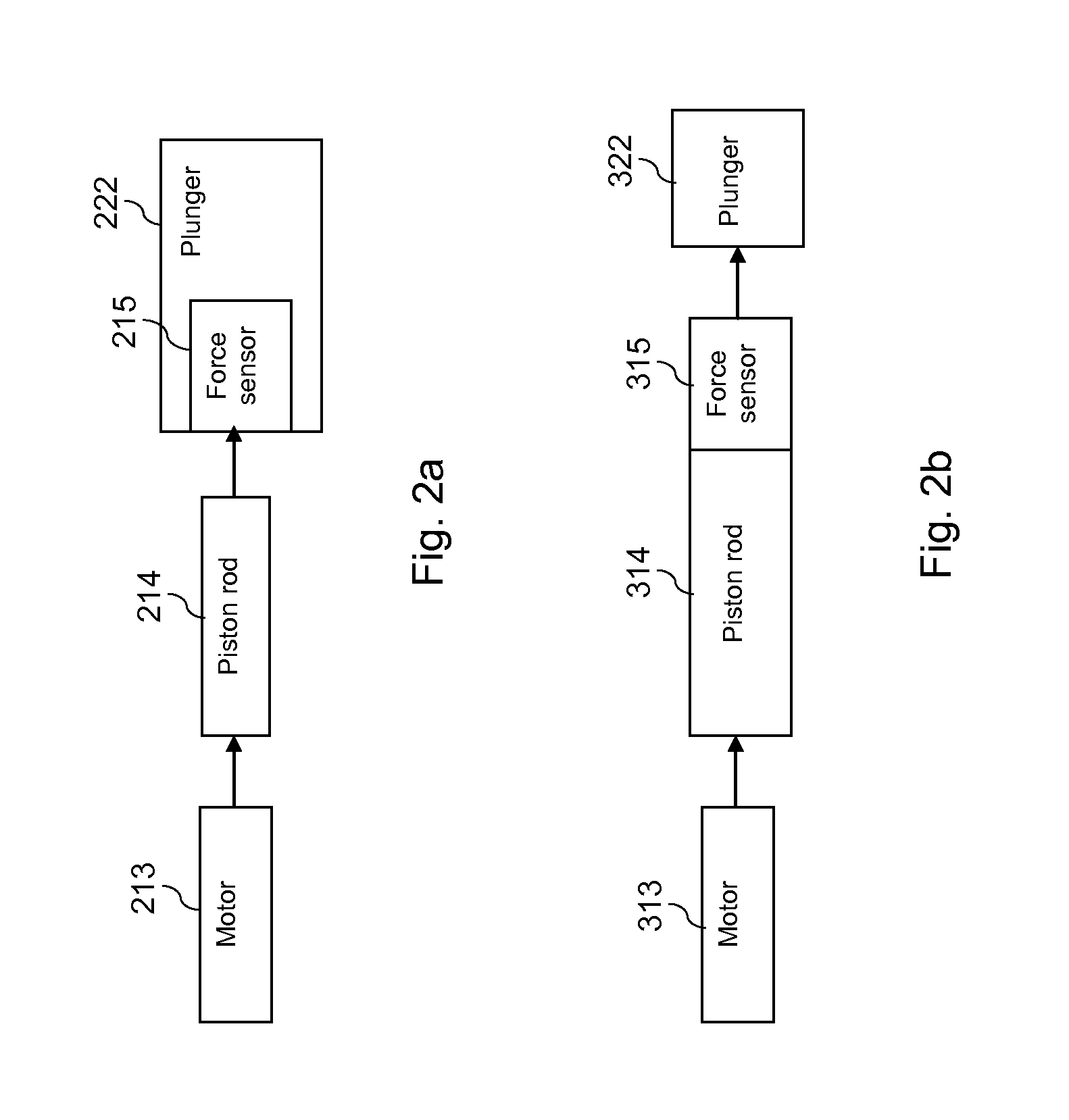
The invention proposes a method and apparatus for controlling the torque provided by a motor of an injection device based on the force required to move a plunger in a cartridge. By measuring the force, the motor can adjust the current applied to it, reducing energy waste and prolonging battery life. The proposed approach is flexible and can adapt to changes in operating cycles, while still ensuring effective movement of the plunger. The force sensor can be integrated in the piston rod or arranged between the piston rod and the plunger, making it easy to implement in exchangeable cartridges. The resulting energy-efficient control of the motor can make a significant difference in battery life, and the proposed method and apparatus can provide reliable and consistent results even in situations where there is no relative movement between the plunger and an element interacting with it.

Problems solved by technology

As a result, the energy efficiency is not optimal.

Method used


Image

  • Controlling a motor of an injection device
  • Controlling a motor of an injection device
  • Controlling a motor of an injection device

Examples


Embodiment Construction

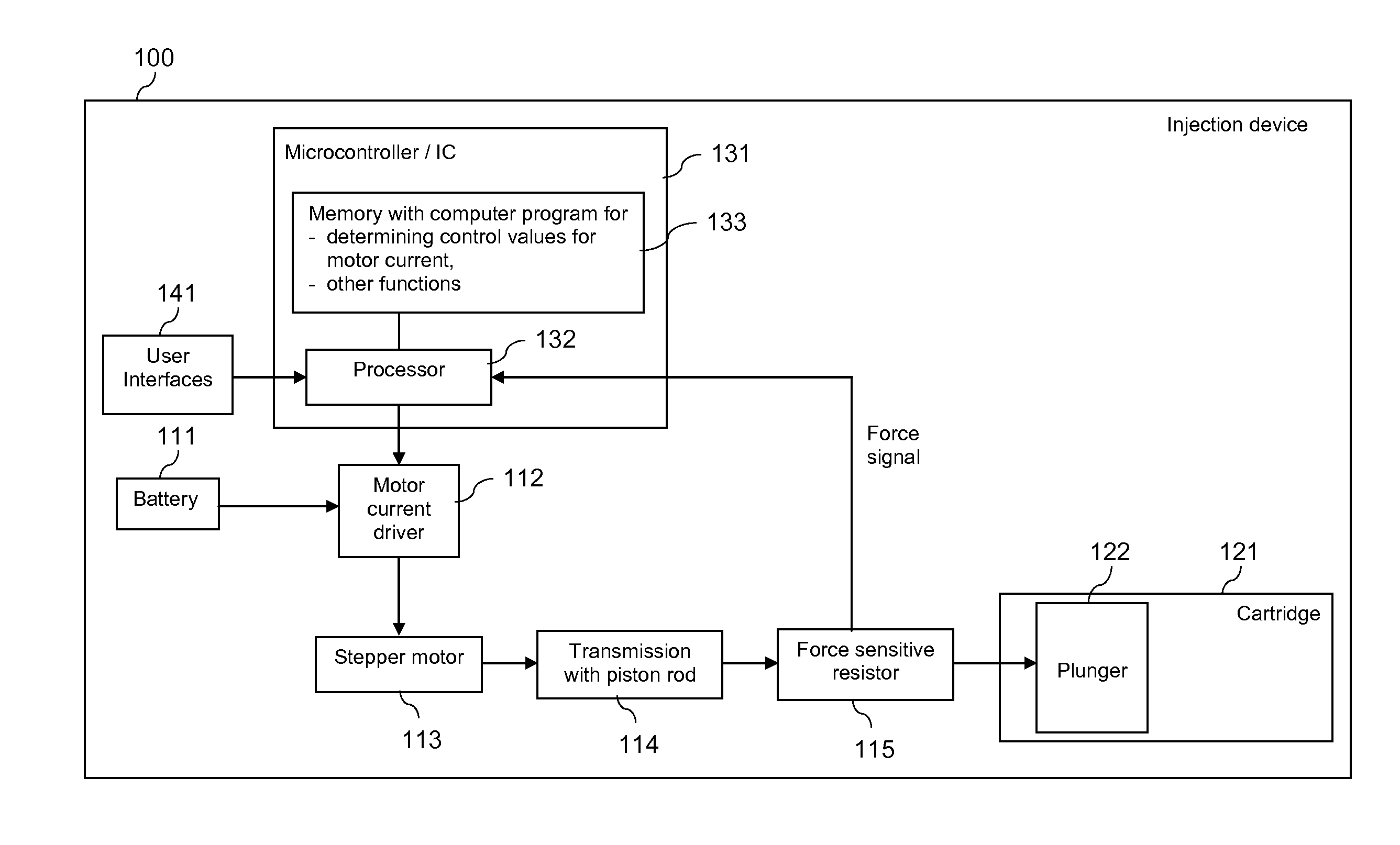
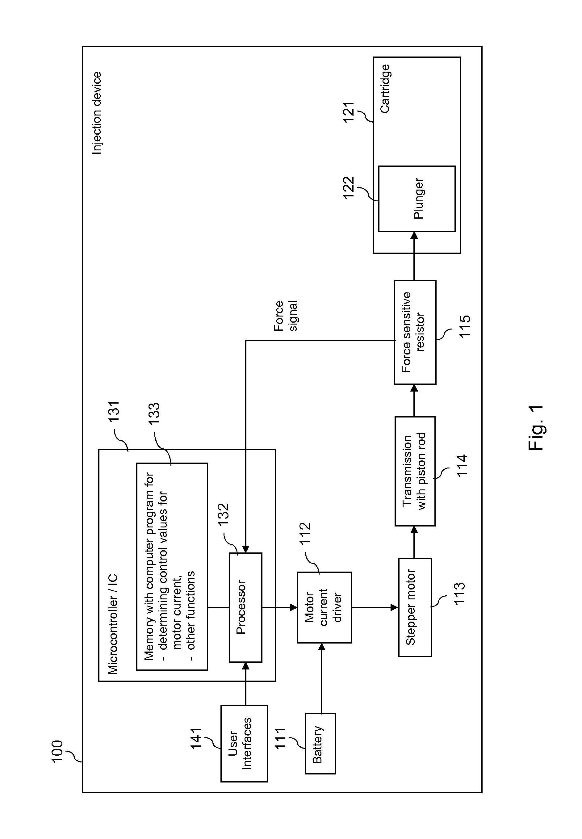
[0042]FIG. 1 is a schematic block diagram, which presents an injection device or apparatus 100 with a motor control according to an exemplary embodiment of the invention.

[0043]The injection device 100 could be for instance an injection pen, such as an insulin pen or an injection pen for another medicament.

[0044]The injection device 100 may comprise a battery 111. The battery can be exchangeable or non-exchangeable. It can further be rechargeable or non-rechargeable.

[0045]The battery 111 is arranged to supply power to a motor current driver 112 of the injection device 100. The motor current driver 112 is linked to a motor, for example to a stepper motor 113 of the injection device 100. The stepper motor 113 interacts with a transmission 114 of the injection device 100. The transmission 114 may comprise for example a piston rod that is moved by the stepper motor 113. The transmission 114 may further comprise a transmissions gear or gearbox, for example to reduce the speed and increase...


PUM


Abstract

In order to improve the energy efficiency of an injection device 100, a current is caused to be applied to a motor 113 of the injection device 100, which is related to a signal from a force sensor 115. The signal represents a force that is applied by the motor 113 to a plunger 122 of a cartridge 121.

Description

FIELD OF THE INVENTION[0001]The invention relates to the field of injection devices, and more specifically to the control of a motor of an injection device for a medicament.BACKGROUND OF THE INVENTION[0002]An injection device, for example an injection pen, can be driven electromechanically by using a motor, which drives a transmission to force a liquid substance out of a container.[0003]The container may be a cartridge, for example for a medicament. The cartridge may have a cylindrical body made of glass, plastics, and / or the like. A first end of the cartridge may be closed by a septum which may be pierced by a needle. A second end of the cartridge may be closed by a plunger which is movable inside the cylindrical body of the cartridge to force out the liquid substance or medicament through the needle in the pierced septum.[0004]With direct current motors, there is a direct relationship between the current consumption of the motor and the output torque. That is, the electrical power...

Claims


Application Information

Patent Timeline
IPC IPC(8): A61M5/20
CPCA61M5/1452A61M5/172A61M5/20A61M2205/8212A61M5/31546A61M2005/31588A61M2205/332A61M5/31525
Inventor MULLER-PATHLE, STEPHANNESSEL, CHRISTIANEISSENGARTHEN, CHRISTOPHDURRANI, NAVID
Owner SANOFI AVENTIS DEUT GMBH
Learn More