
Flex Shaft With Crimped Lock Sleeve For Power Operated Rotary Knife

a technology of flexible shaft and lock sleeve, which is applied in the direction of mechanical equipment, manufacturing tools, couplings, etc., can solve the problems of lubricant leakage the leakage of lubricant between the drive transmitting shaft and the outer casing at the handle assembly coupling end of the flexible shaft drive transmission is typically a much greater problem, and the problem persists. to achieve the effect of reducing the leakag

Active Publication Date: 2013-08-15
BETTCHER INDUSTRIES
View PDF2 Cites 11 Cited by
  • Summary
  • Abstract
  • Description
  • Claims
  • Application Information

AI Technical Summary

Benefits of technology

The present disclosure relates to a flexible shaft drive transmission that is used in power operated tools. The transmission includes an outer casing with a bushing and lubricant, and an elongated drive transmitting shaft with a coupler fitting that fits into the bushing. The coupler fitting includes a body and an enlarged head that provides a seal to prevent leakage of lubricant and allows for limited movement of the shaft in the outer casing. The transmission also includes a driver assembly with a tube assembly and a driver shaft assembly that is connected to the coupler fitting. The technical effects of this disclosure include improved durability and efficiency of the flexible shaft drive transmission and improved performance of the power operated tool.

Problems solved by technology

One recurring problem with respect to the handle assembly coupling end of the flexible shaft drive transmission is that lubricant would tend to leak out between the shaft and the outer casing.
Thus, leakage of lubricant between the drive transmitting shaft and the outer casing at the handle assembly coupling end of the flexible shaft drive transmission typically is a much greater problem than at the motor coupling end.
However, the problem persisted.
If sufficient lubricant leaks out between the drive transmitting shaft and the outer casing, undesirable friction and heat will be generated by contact between the rapidly rotating drive transmitting shaft and the stationary outer casing.
Without the periodic disassembly of the shaft drive transmission to inject new lubricant into the outer casing of prior flexible shaft drive transmissions, the operating life of the drive transmitting shaft and the outer casing would be significantly reduced because of increased heat and wear resulting from lack of sufficient lubricant.
However, periodic maintenance of the shaft drive transmission, like any required maintenance, is costly in terms of both labor required for maintenance and downtime of the equipment.

Method used


Image

  • Flex Shaft With Crimped Lock Sleeve For Power Operated Rotary Knife
  • Flex Shaft With Crimped Lock Sleeve For Power Operated Rotary Knife
  • Flex Shaft With Crimped Lock Sleeve For Power Operated Rotary Knife

Examples


second exemplary embodiment

Flexible Shaft Drive Transmission

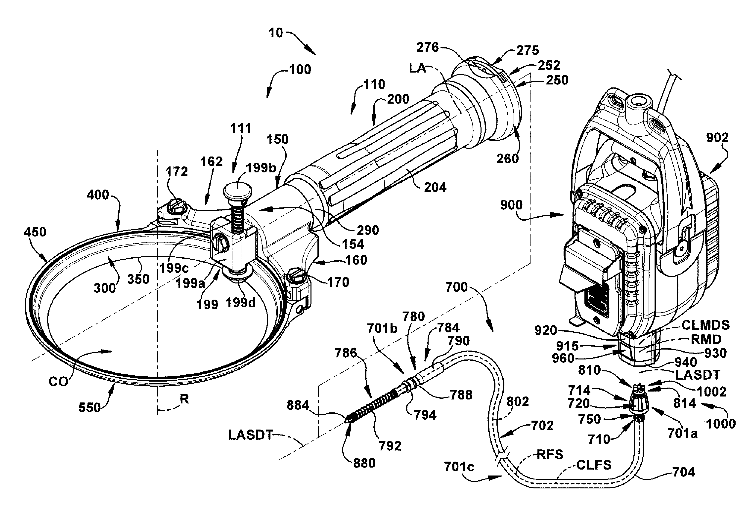
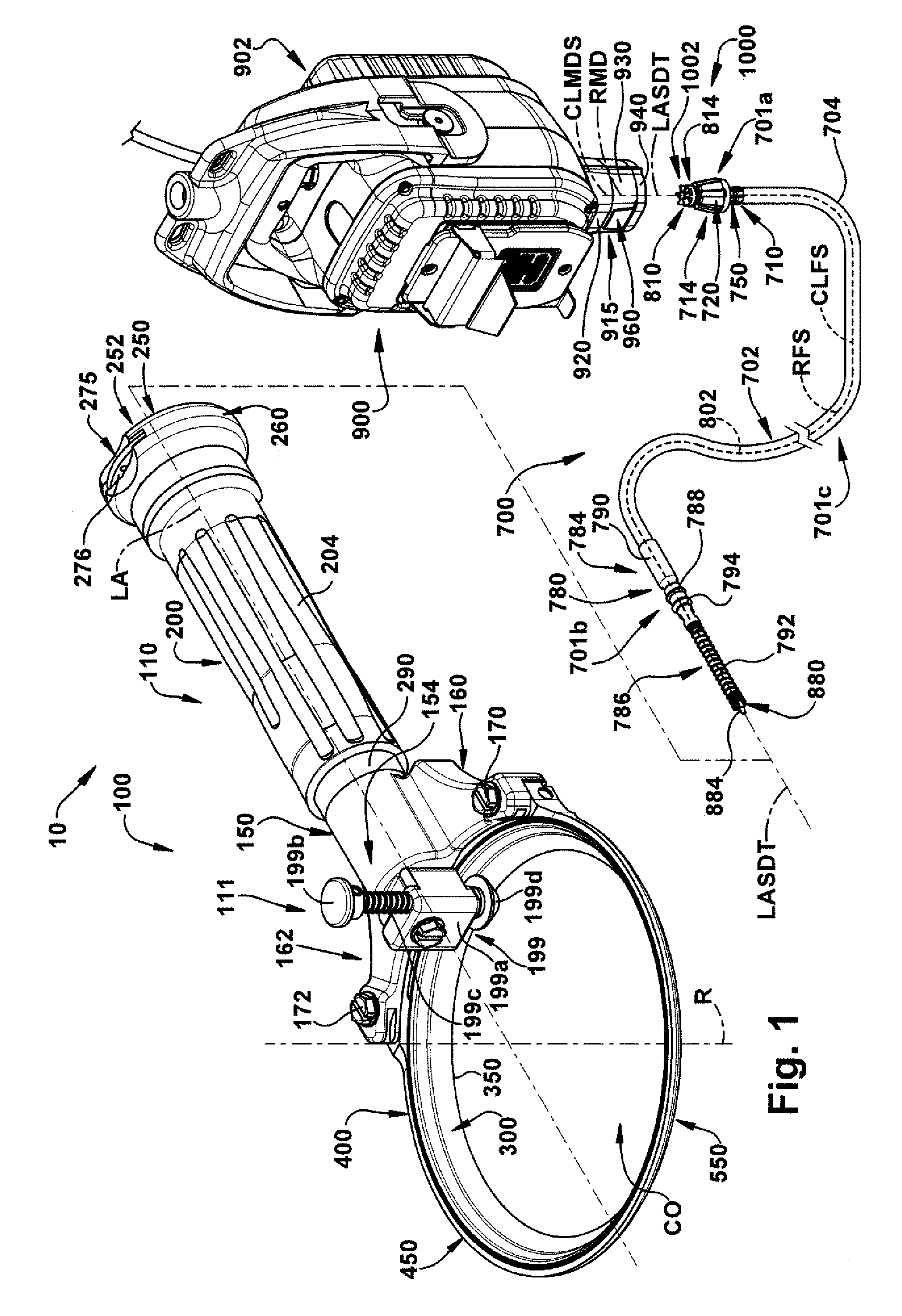
[0165]A second exemplary embodiment of a flexible shaft drive transmission assembly of the present disclosure is shown generally 1700 in FIGS. 29-31. The flexible shaft drive transmission assembly 1700, like the flexible shaft drive transmission 700 previously described, is configured to transmit rotational power from the drive motor 901 to a power operated tool, such as the power operated rotary knife 100. The flexible shaft drive transmission assembly 1700 includes a flexible drive shaft transmission 1701 and a driver assembly 2000. The flexible drive shaft transmission 1701 includes a first or motor end portion 1701a, a second or tool end portion 1701b and an elongated, flexible central portion 1701c extending between the motor end portion 1701a and the tool end portion 1701b. A length of the flexible drive shaft transmission 1701 will depend upon the application, but may range in length from three to six feet or more. The driver assembly 2000 is ...

third exemplary embodiment

Flexible Shaft Drive Transmission

[0210]A third exemplary embodiment of a flexible shaft drive transmission assembly of the present disclosure is shown generally 4700 in FIGS. 46-49. The flexible shaft drive transmission assembly 4700, like the flexible shaft drive transmissions 700, 1700 previously described, is configured to transmit rotational power from the drive motor 901 to a power operated tool, such as the power operated rotary knife 100. The flexible shaft drive transmission assembly 4700 includes a flexible shaft drive transmission 4701 and a driver assembly, not shown. The driver assembly of the flexible shaft drive transmission assembly 4700 is substantially identical in structure and function to the driver assembly 2000 described previously with respect to the flexible shaft drive transmission assembly 1700 and, for brevity, will not be repeated. The flexible shaft drive transmission assembly 4700, including the shaft drive transmission 4701 and the driver assembly, tran...


PUM


Abstract

A method of assembling a flexible shaft drive transmission (4701) coupled between a drive motor and a power operated tool including the steps of: providing a drive transmitting shaft assembly (4800) including a flexible, elongated flex shaft (4702); providing an outer casing assembly (4702) including an outer casing (4704) defining a longitudinally extending throughbore and having a motor end (4710) and a tool end (4780); sliding a lock sleeve (4750) onto the motor end of the outer casing to a recessed position with respect to the motor end of the casing; inserting the motor end of the flex shaft through the tool end of the outer casing; affixing a driven fitting (4814) to the motor end of the flex shaft; advancing the lock sleeve to overlie the motor end of casing; and affixing a casing portion (4762) of the lock sleeve to the outer casing.

Description

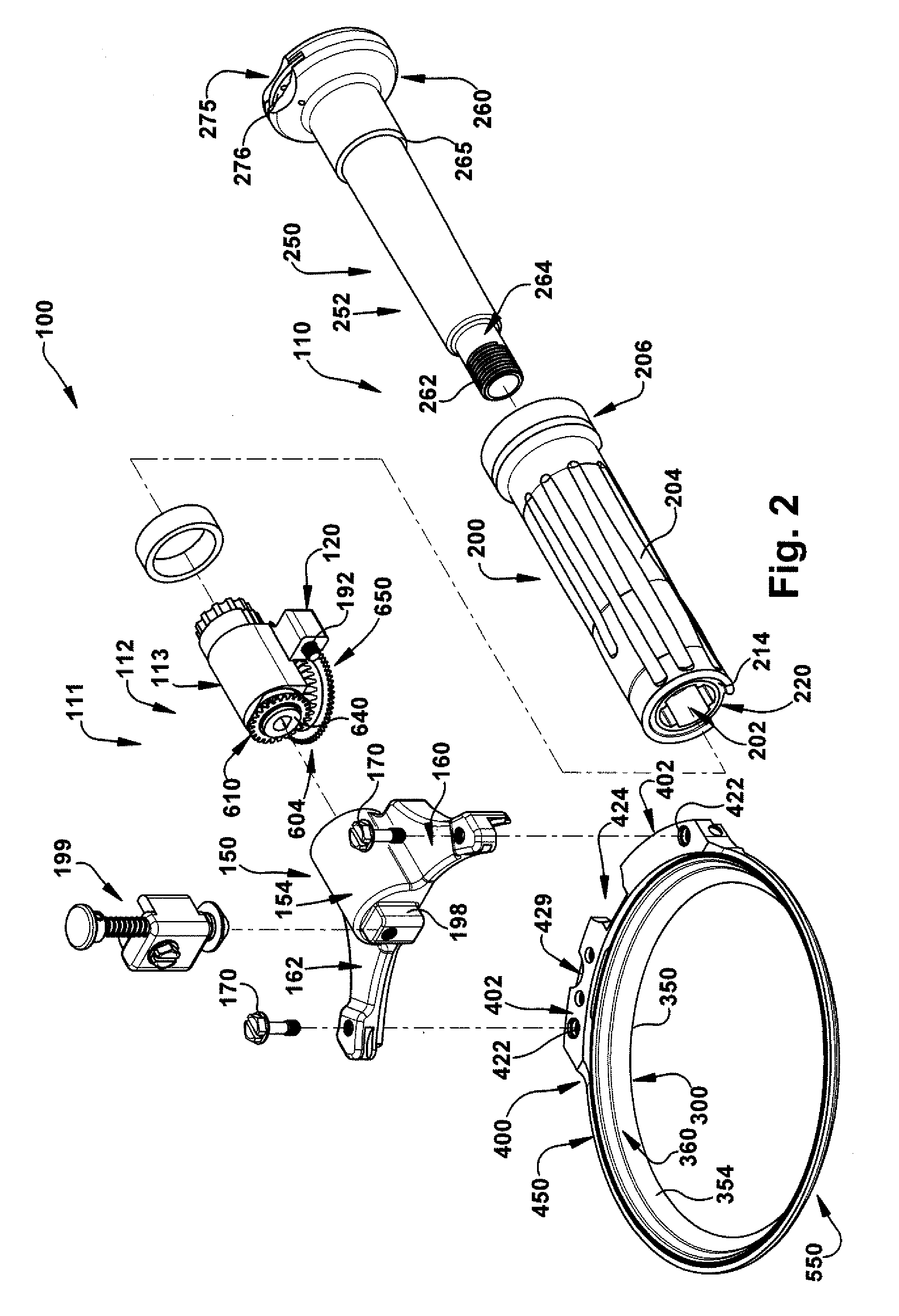
CROSS-REFERENCE TO RELATED APPLICATIONS[0001]The present application is a continuation-in-part application of co-pending U.S. application Ser. No. 13 / 344,760, filed Jan. 6, 2012 and entitled FLEX SHAFT-DRIVE MOTOR CONNECTION FOR POWER OPERATED ROTARY KNIFE. The present application claims priority from above-identified application Ser. No. 13 / 344,760, which is incorporated herein in its entirety by reference, for all purposes. The present application is also a continuation-in-part application of co-pending U.S. application Ser. No. 13 / 434,403, filed Mar. 29, 2012 and entitled FLEX SHAFT-TOOL CONNECTION FOR POWER OPERATED ROTARY KNIFE. The present application claims priority from above-identified application Ser. No. 13 / 434,403, which is incorporated herein in its entirety by reference, for all purposes.TECHNICAL FIELD[0002]The present disclosure relates to a flexible shaft drive transmission including an elongated drive transmitting shaft assembly rotatable within an outer casing ass...

Claims


Application Information

Patent Timeline
IPC IPC(8): F16C1/02
CPCF16C1/02A22C17/00B26B25/002F16C1/24A22B5/165Y10T29/49826F16C1/06F16C1/08F16D1/10F16D2001/102Y10T29/49925A22C17/12
Inventor MASCARI, NICHOLAS A.
Owner BETTCHER INDUSTRIES
Learn More