
Electric spindle and machine tool

A technology of electric spindle and rotating shaft, which is applied in the field of machine tools, can solve the problems of machine tool table and machined parts pollution, lubricating oil leakage, electric spindle oil leakage, etc., and achieve the effect of reducing lubricating oil leakage, relatively smooth rotation, and keeping clean

Inactive Publication Date: 2020-06-30
GREE ELECTRIC APPLIANCES INC OF ZHUHAI
View PDF11 Cites 1 Cited by
  • Summary
  • Abstract
  • Description
  • Claims
  • Application Information

AI Technical Summary

Problems solved by technology

[0002] The existing electric spindle has a lubricating oil path, such as the electric spindle disclosed in the Chinese patents with publication numbers CN101549467A, CN102078973A, CN106695450A and CN207372312U. The lubricating oil path is connected to the bearing between the base body and the rotating shaft. However, the existing electric spindle is prone to oil leakage, especially when the electric spindle is in the running state with the shaft end facing down, the lubricating oil is easy to leak from the shaft end of the electric spindle, which is easy to damage the machine tool workbench and the machine tool. Processing parts cause pollution

Method used


Image

  • Electric spindle and machine tool
  • Electric spindle and machine tool

Examples


Embodiment Construction

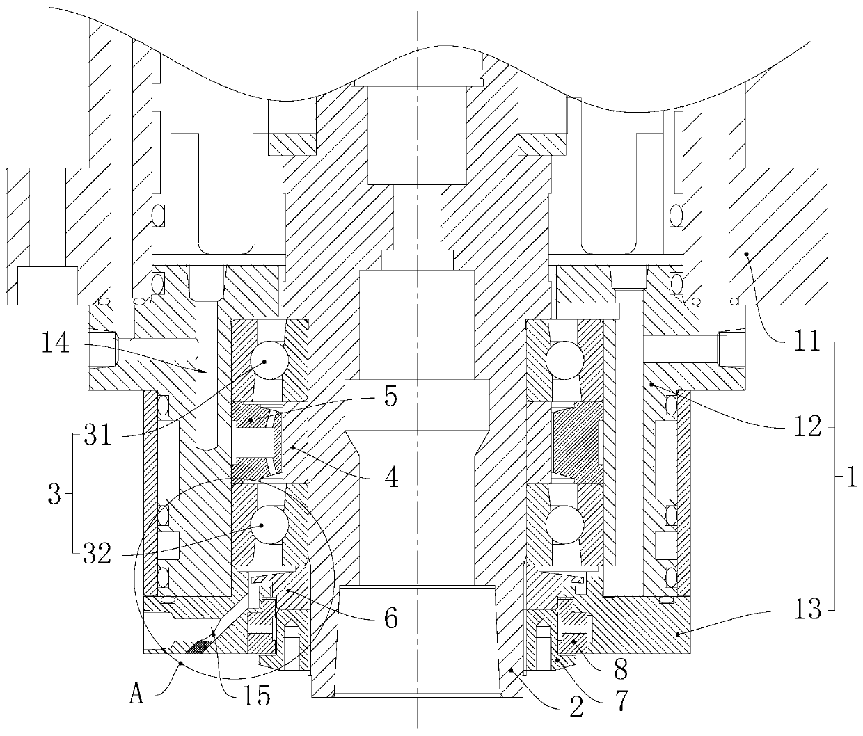
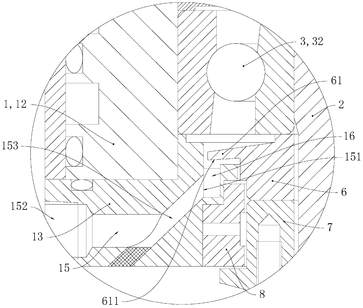
[0025] Please refer to figure 1 and figure 2 The electric spindle of this embodiment includes a base body 1, a rotating shaft 2, an end bearing 3, a seal ring 6, an air-tight structure 8 and a lock nut 7, and the base body 1 includes a cylinder body 11 fixedly connected, a bearing mounting seat 12 and a bearing press The cover 13, cylinder 11, bearing mounting seat 12 and bearing gland 13 are distributed vertically from top to bottom. Stretch down.

[0026] The end bearing 3 is installed between the bearing mounting seat 12 and the rotating shaft 2, the sealing ring 6 and the locking nut 7 are fixed on the rotating shaft 2, the rotating shaft 2 realizes the relative rotation with the base 1 through the end bearing 3, and the locking nut 7 It is threadedly connected with the rotating shaft 2.

[0027] A lubricating oil passage 14 is provided on the base body 1 , and the lubricating oil passage 14 is distributed on the cylinder body 11 and the bearing mounting seat 12 , and ...


PUM


Abstract

The invention relates to the field of machine tools. An electric spindle comprises a base body and a rotating shaft which is arranged in the base body in the radial direction; bearings are arranged between the rotating shaft and the base body, a lubricating oil route is arranged in the base body, and a shaft end sealing structure is arranged between the base body and the rotating shaft; a leakingoil collection route is arranged in the base body, the first end of the leaking oil collection route is positioned on the inner wall of the base body, the second end of the leaking oil collection route is positioned on the outer wall of the base body, and the leaking oil collection route is for collecting lubricating oil which leaks from the shaft end sealing structure in the axial direction. Through the arrangement of the leaking oil collection route, in application of the electric spindle, lubricating oil leaking from the shaft end sealing structure is collected into the leaking oil collection route so the lubricating oil is not prone to further leaking out, in the axial direction of the electric spindle through the gap between the rotating shaft and the base body, and therefore, lubricating oil leak from the electric spindle is effectively reduced.

Description

technical field [0001] The invention relates to the field of machine tools, in particular to an electric spindle and a machine tool. Background technique [0002] The existing electric spindle has a lubricating oil path, such as the electric spindle disclosed in the Chinese patents with publication numbers CN101549467A, CN102078973A, CN106695450A and CN207372312U. The lubricating oil path is connected to the bearing between the base body and the rotating shaft. However, the existing electric spindle is prone to oil leakage, especially when the electric spindle is in the running state with the shaft end facing down, the lubricating oil is easy to leak from the shaft end of the electric spindle, which is easy to damage the machine tool workbench and the machine tool. Processing parts cause pollution. Contents of the invention [0003] One of the objects of the present invention is to provide an electric spindle which is advantageous in preventing leakage of lubricating oil....

Claims


Application Information

Patent Timeline
IPC IPC(8): F16N1/00F16N7/00F16N31/02F16C35/04F16J15/324B23Q11/12B23B19/02
CPCB23Q1/70B23Q11/12F16C35/04F16J15/324F16N1/00F16N7/00F16N31/02F16N2210/14
Inventor 刘永连汪正学罗慧琪
Owner GREE ELECTRIC APPLIANCES INC OF ZHUHAI
Learn More