Centric clamping device

a clamping device and centric technology, applied in the direction of chucks, mechanical equipment, manufacturing tools, etc., can solve the problems of inability to achieve the clamping task, inability to achieve centric clamping with a uniform clamping pressure on all clamping jaws, and inability to reliably centric clamp blanks with shape deviations

Inactive Publication Date: 2013-08-15
KARLEIN BIRGITT
View PDF10 Cites 10 Cited by
  • Summary
  • Abstract
  • Description
  • Claims
  • Application Information

AI Technical Summary

Benefits of technology

[0057]Furthermore, it is advantageous in the realization to position the internal basic clamping supports in the symmetry respectively between the two coupled external basic clamping supports. Here, the internal basic clamping supports can be designed with a predominantly long jaw guide almost reaching the axis of rotation, wherein the external basic clamping supports have a larger distance to the axis of rotation for spatial reasons, which does not do any harm, however, as the external basic clamping supports and respectively the clamping jaws mounted thereto are used in particular for clamping workpieces with large diameters.
[0058]In particular in connection with a perpendicular axis of rotation and a heavy workpiece weight on the clamping device it is particularly advantageous to attach at least two load supports to the device support, or to make it possible to attach them, wherein the abutting workpiece weight is supported by the load supports and wherein the workpiece does not abut on the clamping jaws in the direction of the axis of rotation. In this way, it is ensured that the clamping jaws can move freely in relation to one another and that the solution according to the invention can be used unconditionally.

Problems solved by technology

It is apparent that such a clamping task cannot be accomplished with a normal three- or four-jaw chuck.
What is disadvantageous with this solution is, however, that centric clamping with a uniform clamping pressure on all clamping jaws is still not possible, in particular in connection with defects in shape.
There is no real possibility for reliable centric clamping of blanks with shape deviations.
In particular the attempt at centric clamping of the workpiece leads to a significant clamping effort when several concentricity checks and subsequent recentering of the workpiece become necessary.
Furthermore, the chuck has to be rotated each time to that end, or the machine operator has to go around the face chuck when working at a big rotary table.
Consequently, it is not at all guaranteed with this clamping method that all jaws abut on the workpiece with the same clamping pressure.
In particular in connection with clamping thin-walled workpieces or rings, clamping errors can occur.
A particularly problematic situation arises when thin-walled workpiece blanks are not perfectly round.
This can lead to misjudgements on the part of the machine operator when concentricity checks at the workpiece reveal constant deviations.
Consequently, the other two pairs of pendulum jaws can only be adjusted toward the workpiece without allowing an exact centering in the second orientation thereof, however.

Method used


Image

  • Centric clamping device
  • Centric clamping device
  • Centric clamping device

Examples


Embodiment Construction

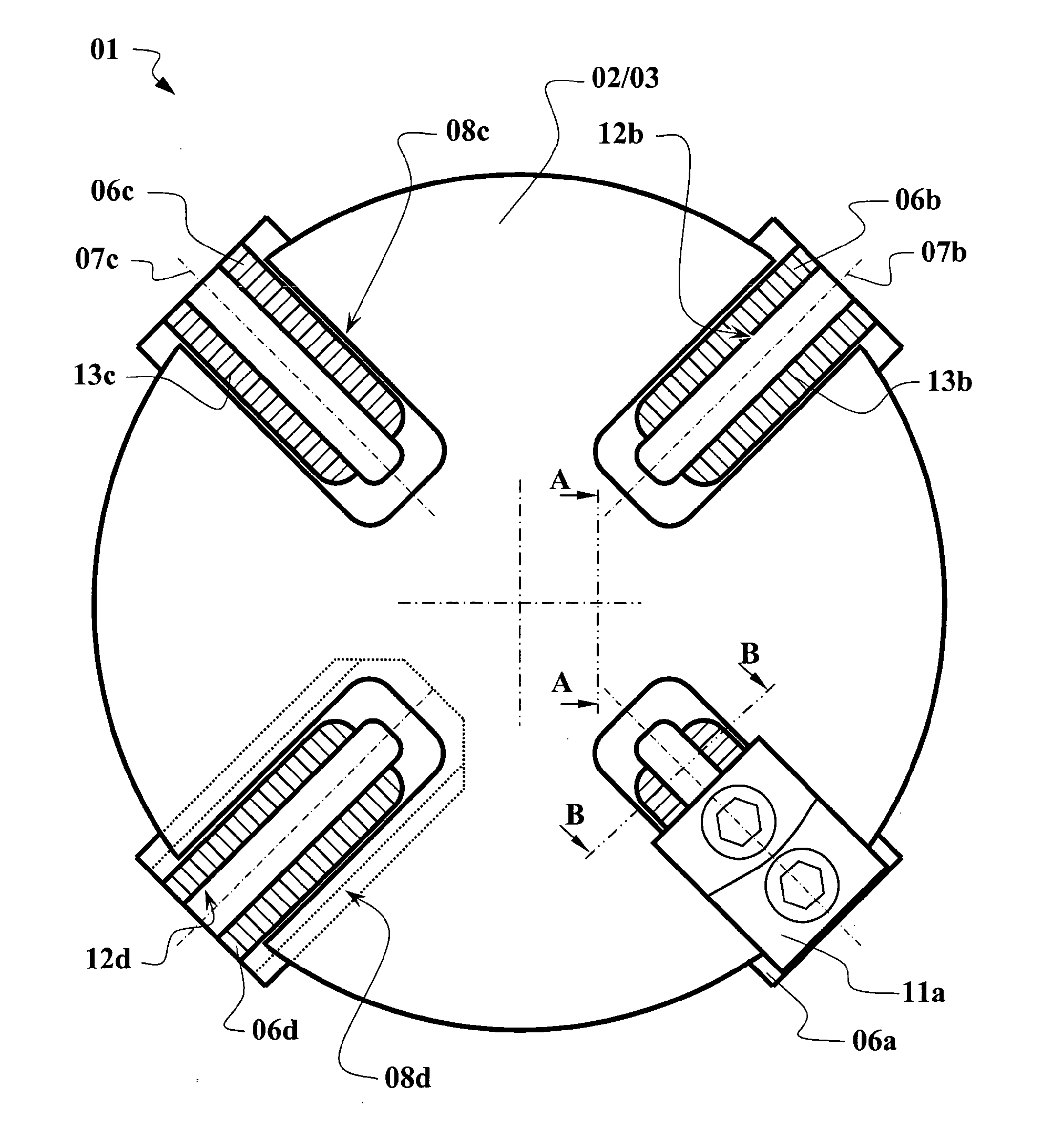
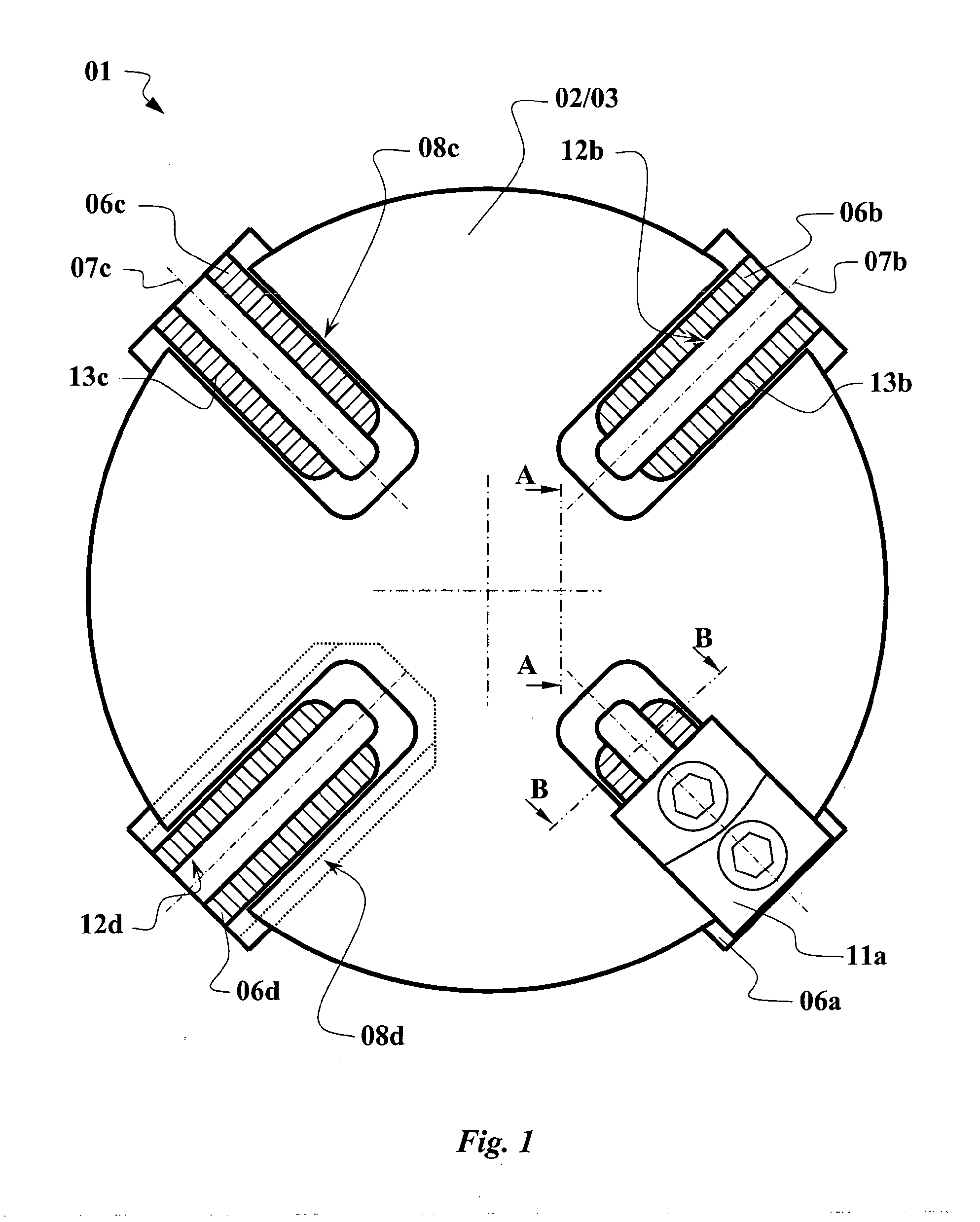
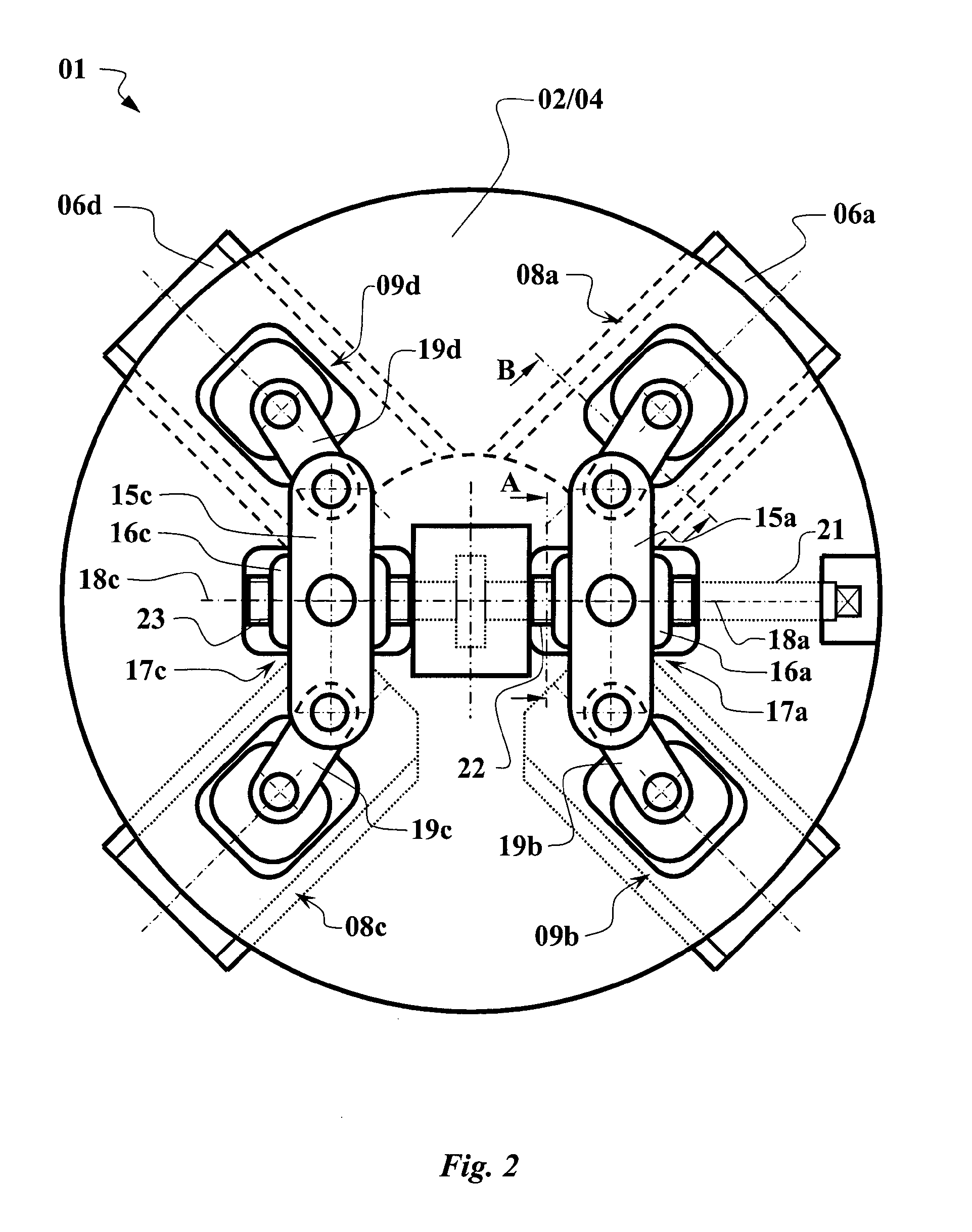
[0075]Referring to the drawings in particular, in FIG. 1, a first embodiment of a clamping device according to the invention 01 is outlined as an example. First of all, it shows the device support 02, respectively the upper housing section 03 of the device support 02 in the circular form. In the device support 02, there are guide grooves in the form of the support guide 08a to 08d. The four basic clamping supports 06a to 06d are inserted into these guide grooves. Along the respective support orientations 07a to 07d, the respective basic clamping supports 06 can be slid in the support guides 08. Furthermore, a clamping jaw 11a on the basic clamping support 06a is outlined as an example. Here, the clamping jaw 11 can be moved along jaw guides 12 in parallel with the support guides 06. In this respect, the clamping jaw 11 can also be displaced radially in relation to the axis of rotation. In order to lock the position of the clamping jaw 11 in relation to the basic clamping support 06,...


PUM


Abstract

A clamping device (01), for use on a lathe, includes a plurality of basic clamping supports (06), which can be moved in a star-shaped formation in relation to an axis of rotation and on each of which a clamping jaw (11) for clamping workpieces can be attached. The basic clamping supports (06) can be adjusted simultaneously by means of an adjusting drive (21, 36) of the clamping device (01). At least two basic clamping supports (06) are coupled directly or indirectly to one another by an outer rocker (15). At least in the middle of the adjusting path, a limited inward displacement of a basic clamping support (06a, 06c, and 06b, 06d, respectively) leads to a swiveling of the outer rocker (15a, 15c) and an outward displacement of the other coupled basic clamping support (06b, 06d, and 06a, 06c, respectively).

Description

CROSS REFERENCE TO RELATED APPLICATIONS[0001]This application is a United States National Phase application of International Application PCT / DE2011 / 000345 and claims the benefit of priority under 35 U.S.C. §119 of German Application DE 10 2010 023 797.3 filed Jun. 15, 2010, the entire contents of which are incorporated herein by reference.FIELD OF THE INVENTION[0002]The invention relates to a clamping device for use with a lathe or the like for clamping workpieces by means of a plurality of clamping jaws.BACKGROUND OF THE INVENTION[0003]Chucks for lathes in different designs are well-known from the state of the art. For clamping round workpieces, the state of the art normally uses a three-jaw chuck with lathes and a so-called four jaw chuck for clamping square workpieces. In this regard there is no need for further elaboration. Normal chucks have in common that the plurality of clamping jaws—normally three or four—are simultaneously adjusted manually, hydraulically or electrically a...

Claims


Application Information

Patent Timeline
Patent Type & Authority Applications(United States)
IPC IPC(8): B23B31/02
CPCB23B31/16B23B31/16045Y10T82/2552B23B2231/22B23B31/02B23B2215/64B23B2231/30Y10T82/2572Y10T279/1913Y10T82/2579Y10T279/1961Y10T279/19
Inventor KARLEIN, BIRGITTKARLEIN, EUGEN
Owner KARLEIN BIRGITT
Why Eureka
Try Eureka