Geometry of heat exchanger with high efficiency

a heat exchanger and geometry technology, applied in the direction of indirect heat exchangers, stationary tubular conduit assemblies, lighting and heating apparatus, etc., to achieve the effect of high energy efficiency

Active Publication Date: 2013-08-15
TRUSTEES OF DARTMOUTH COLLEGE THE
View PDF1 Cites 82 Cited by
  • Summary
  • Abstract
  • Description
  • Claims
  • Application Information

AI Technical Summary

Problems solved by technology

However, most applications in which heat transfer is performed, such as air-conditioning systems, rely on energy-consuming fans and blowers to force air, water or other fluids through high-drag configurations such as cross-tubes, radiator fins and brush-like surfaces.

Method used


Image

  • Geometry of heat exchanger with high efficiency
  • Geometry of heat exchanger with high efficiency
  • Geometry of heat exchanger with high efficiency

Examples


Embodiment Construction

[0017]The present disclosure may be understood by reference to the following detailed description taken in conjunction with the drawings as described below. For purposes of illustrative clarity, certain elements in the drawings are not drawn to scale.

[0018]It is desirable for heat exchanging systems to impose less friction to fluid motion, consume less mechanical energy, and achieve higher energy efficiency than conventional designs. Such heat exchangers may be useful in applications such as heat recycling in buildings, air-conditioning, and refrigeration, as well as automotive engine cooling and chemical engineering applications. It may also be desirable to reduce mechanical friction associated with heat exchangers used to transfer heat between two fluids by avoiding abrupt geometrical changes.

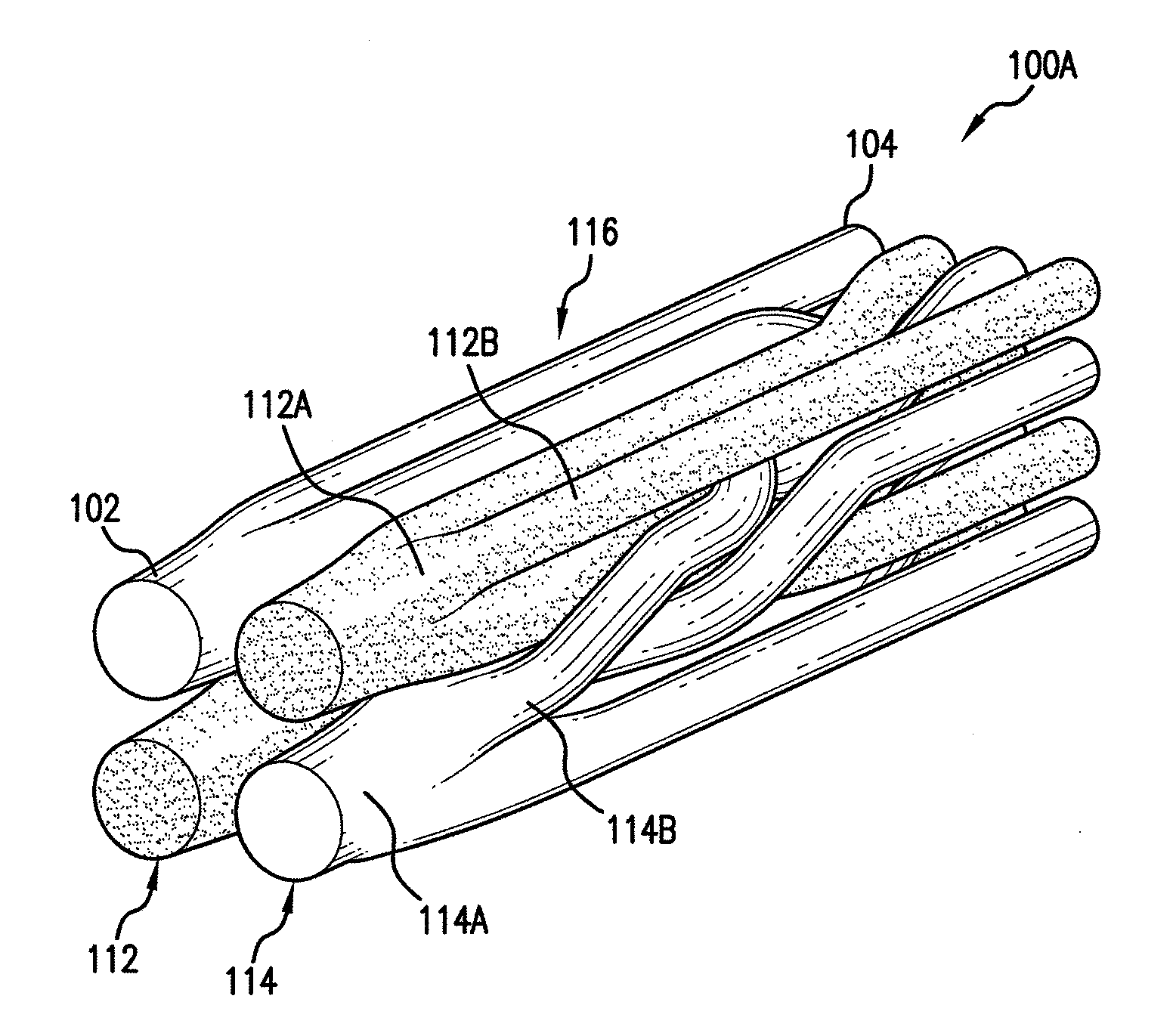
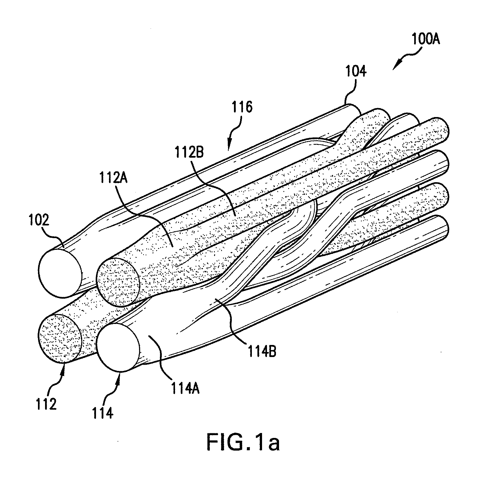
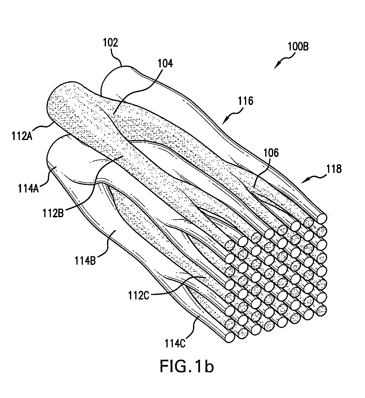
[0019]This application discloses a geometry based on sequential branching of circular passages in sets together with deformation and twisting of formed branches to intermingle passages of one...


PUM

PropertyMeasurementUnit
diameteraaaaaaaaaa
diameteraaaaaaaaaa
lengthaaaaaaaaaa

Abstract

The present disclosure includes geometry of a two-fluid heat exchanger to provide higher energy efficiency than conventional heat exchangers. The geometry is based upon sequential branching of nearly circular passages in sets, followed by some deformation and twisting of the sequential branches that intermingle flow passages of one fluid with flow passages of another fluid. The flow passages gradually vary in dimension from larger branching at fluid entrance and exit to smaller branching in the middle section of the heat exchanger. The heat exchanger is substantially symmetric, with the sequential branching in the first half being mirrored as serial regrouping in the second half. The present disclosure also provides stacking methods and layered manufacturing methods for fabricating the three-dimensional geometry of the heat exchanger.

Description

CROSS-REFERENCE TO RELATED APPLICATIONS[0001]This application claims the benefit of U.S. Provisional Patent Application No. 61 / 314,052, filed Mar. 15, 2010, entitled “Geometry of Heat Exchanger with High Efficiency,” the entire content of which is incorporated herein by reference.BACKGROUND OF THE INVENTION[0002]This application relates to design of heat exchanger for allowing two fluids of different temperatures to exchange heat. More specifically, the design relates to geometry of heat exchangers.[0003]Heat transfer occurs spontaneously whenever there is a temperature difference and, in principle, requires no source of mechanical energy. However, most applications in which heat transfer is performed, such as air-conditioning systems, rely on energy-consuming fans and blowers to force air, water or other fluids through high-drag configurations such as cross-tubes, radiator fins and brush-like surfaces.BRIEF SUMMARY[0004]Embodiments of the present disclosure include geometries of a ...

Claims


Application Information

Patent Timeline
Patent Type & Authority Applications(United States)
IPC IPC(8): F28D7/00B23P15/26
CPCB22F7/002C22C1/08F28D7/0008F28D2021/007Y10T29/4935F28F21/084F28F2210/02B23P15/26F28D7/0041F28F7/02F28D21/0012B33Y80/00B33Y70/00F28D7/0066F28D7/00
Inventor ROISIN, BENOITGRAVES, IAN ESTLE
Owner TRUSTEES OF DARTMOUTH COLLEGE THE
Why Eureka
Try Eureka