
Touch panel

a technology of touch panel and touch panel, applied in the field of panel, can solve the problem of not quickly reverting back, and achieve the effect of favorable ability to restore from deformation

Inactive Publication Date: 2013-08-15
DONGGUAN MASSTOP LIQUID CRYSTAL DISPLAY +1
View PDF4 Cites 4 Cited by
  • Summary
  • Abstract
  • Description
  • Claims
  • Application Information

AI Technical Summary

Benefits of technology

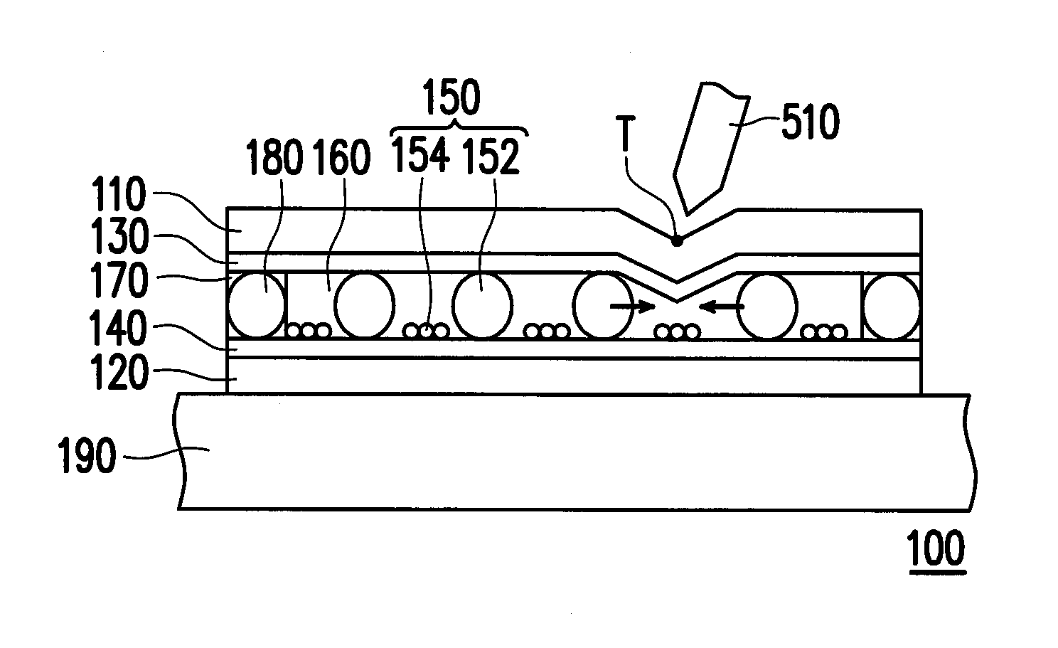
The invention provides a touch panel that can restore itself from deformation. This is achieved by restricting the movement of certain spacers between layers in the touch panel using a second substrate. When pressure is removed, the spacers quickly rebound back to their original position, preventing any erroneous detection due to the deformation of the first substrate. As a result, the touch sensitivity of the touch panel is improved.

Problems solved by technology

However, resulting from the material of the substrate, the substrate may not rapidly revert back to the original planar state after being pressed so that the time extension of the touch sensing signal or the erroneous detection is generated.

Method used


Image

  • Touch panel
  • Touch panel
  • Touch panel

Examples


Embodiment Construction

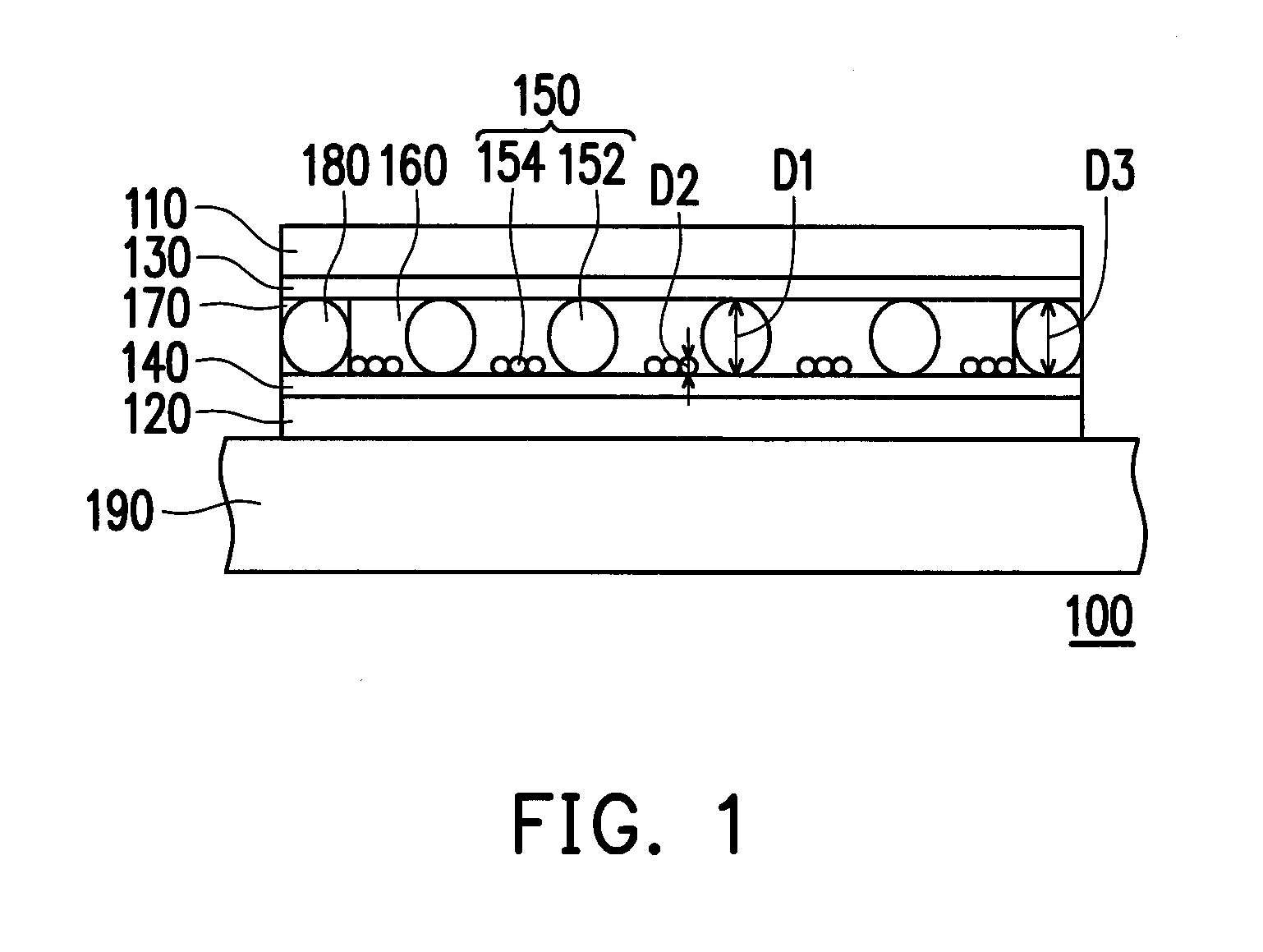
[0028]FIG. 1 is a schematic cross-sectional view illustrating a touch panel according to an embodiment of the invention.

[0029]Referring to FIG. 1, a touch panel 100 includes a first substrate 110, a second substrate 120, a first sensing layer 130, a second sensing layer 140, and a plurality of spacers 150.

[0030]The second substrate 120 is parallel to and opposite to the first substrate 110 in a top-bottom manner.

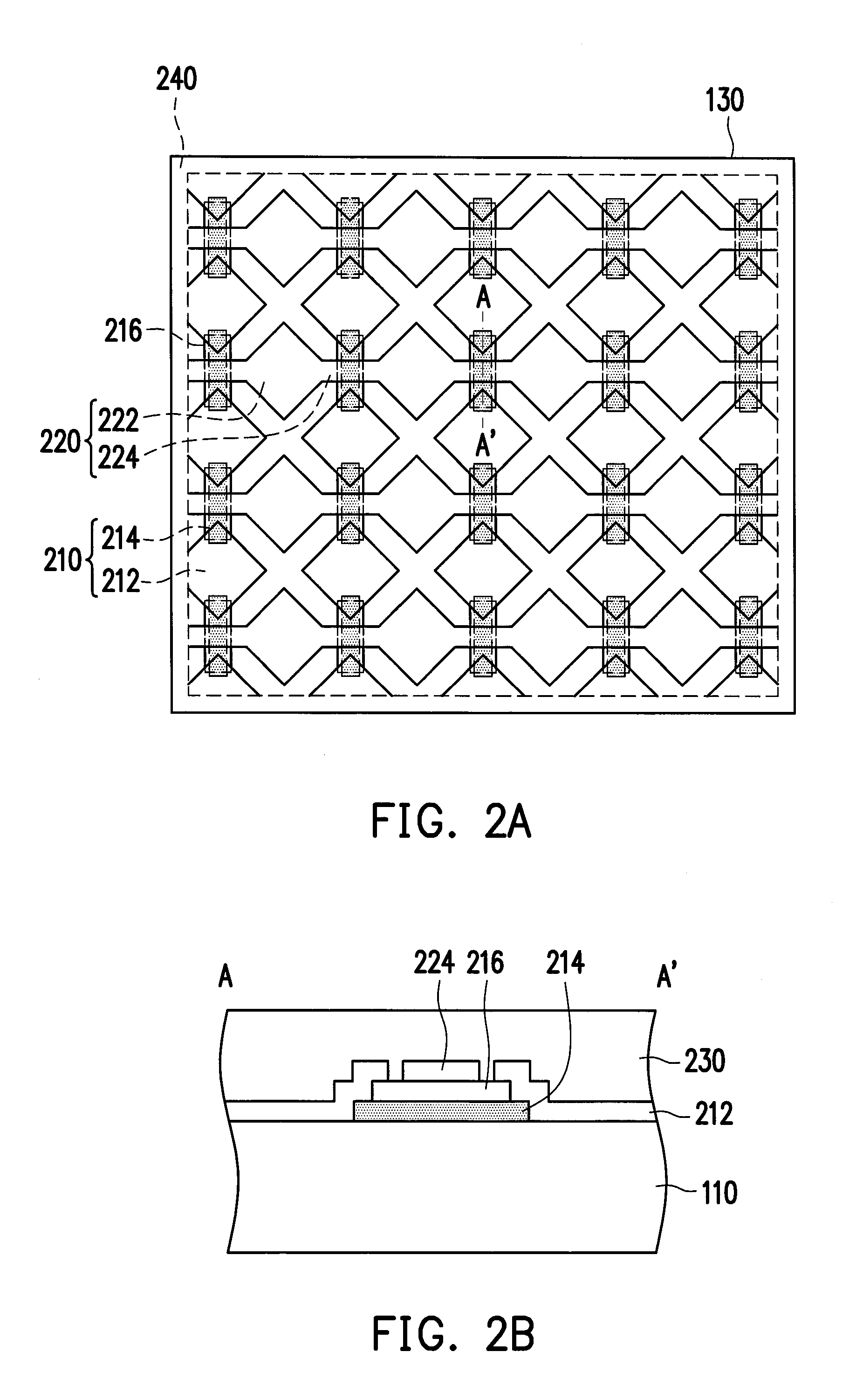
[0031]The first sensing layer 130 is disposed on the first substrate 110 and located between the first substrate 110 and the second substrate 120. The second sensing layer 140 is disposed on the second substrate 120. According to the present embodiment, the second sensing layer 140 is located between the first substrate 110 and the second substrate 120, which should not be construed as a limitation to the invention. In other embodiments, the second sensing layer 140 can be selectively located at a side of the second substrate 120 away from the first substrate 110. The spacer...


PUM


Abstract

A touch panel including a first substrate, a second substrate, a first sensing layer, a second sensing layer, and a plurality of spacers is provided. The second substrate is parallel to and opposite to the first substrate in a top-bottom manner. The first sensing layer is disposed on the first substrate and located between the first substrate and the second substrate. The second sensing layer is disposed on the second substrate. The spacers are located between the first sensing layer and the second sensing layer, and the spacers includes a plurality of movable first spacers and a plurality of second spacers fixed on the second substrate, wherein each of the first spacers is surrounded by a portion of the second spacers.

Description

CROSS-REFERENCE TO RELATED APPLICATION[0001]This application claims the priority benefit of Taiwan application Ser. No. 101104628, filed on Feb. 14, 2012. The entirety of the above-mentioned patent application is hereby incorporated by reference herein and made a part of this specification.BACKGROUND OF THE INVENTION[0002]1. Field of the Invention[0003]The invention relates to a panel. More particularly, the invention relates to a touch panel.[0004]2. Description of Related Art[0005]At present, the touch panels can be generally classified into capacitive, resistive, optical, acoustic, and electromagnetic touch panels, wherein the resistive touch panels and the capacitive touch panels are most popular. Generally, a user can press the resistive touch panel through an object such as an insulating pen and the resistive touch panel detects the touch position of the object through the voltage change generated in the resistive touch panel in response to the pressing of the object. On the o...

Claims


Application Information

Patent Timeline
Patent Type & Authority Applications(United States)
IPC IPC(8): H01H13/10
CPCG06F3/044H01H13/10G06F3/0445G06F3/0446
Inventor WU, YU-HUACHOU, CHENG-YIWANG, CHIH-YUANCHANG, TING-YUHSU, CHING-FULIAO, HSIAO-HUI
Owner DONGGUAN MASSTOP LIQUID CRYSTAL DISPLAY
Learn More