Pipe Coupling

a technology of pipe coupling and pipe body, which is applied in the direction of couplings, mechanical equipment, drilling pipes, etc., can solve the problems of less good sealing capacity and wear on the surface, and achieve the effect of sufficient sealing capacity and improved sealing wear properties

Inactive Publication Date: 2013-08-15
IKM GRUPPEN AS
View PDF4 Cites 35 Cited by
  • Summary
  • Abstract
  • Description
  • Claims
  • Application Information

AI Technical Summary

Benefits of technology

[0014]It is an object of the present invention to present a pipe coupling in which the design of the sealing ele...

Problems solved by technology

Thereby, there will also be a slight displacement between the contact surfaces of the sealing element and the corresponding surface of the respective tubular element and, as a consequence...

Method used


Image

  • Pipe Coupling
  • Pipe Coupling
  • Pipe Coupling

Examples


Embodiment Construction

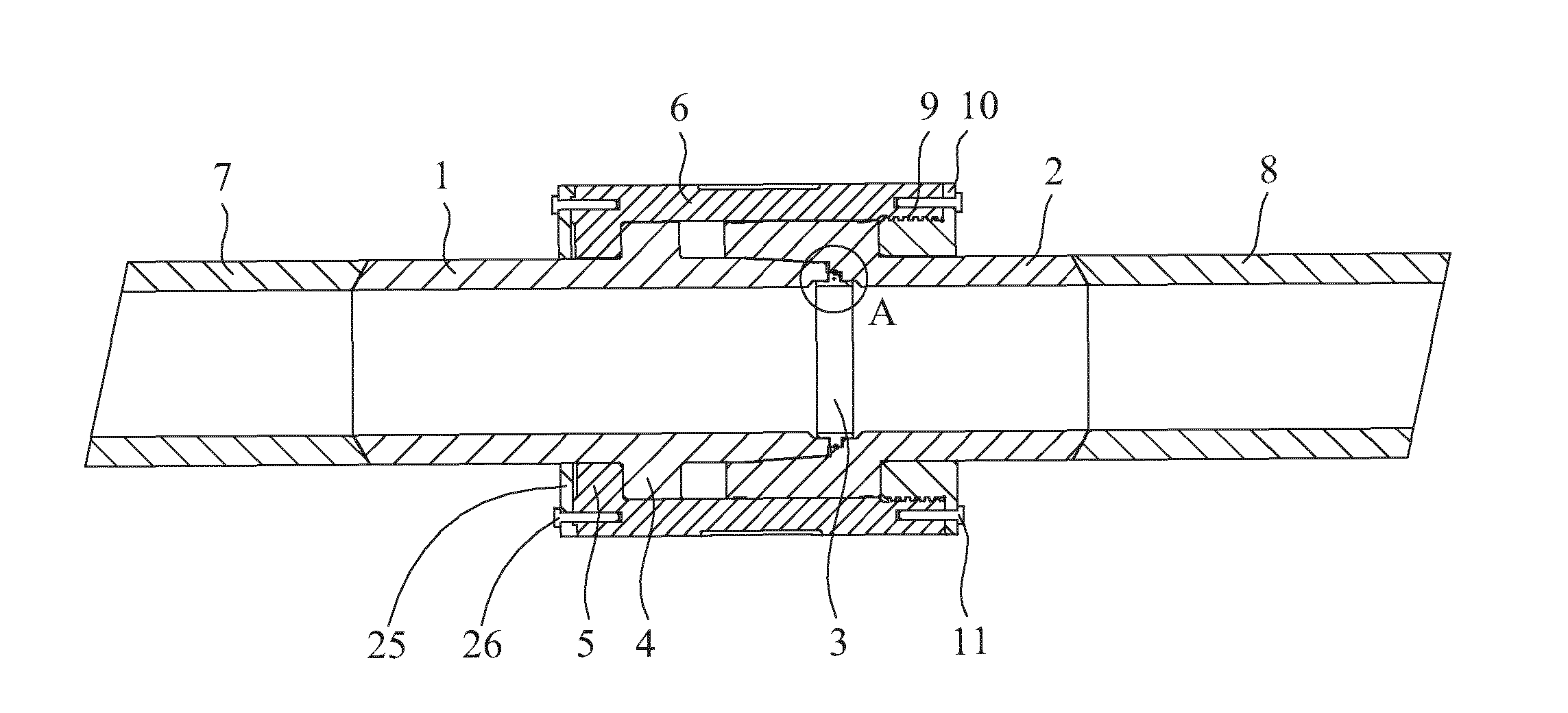
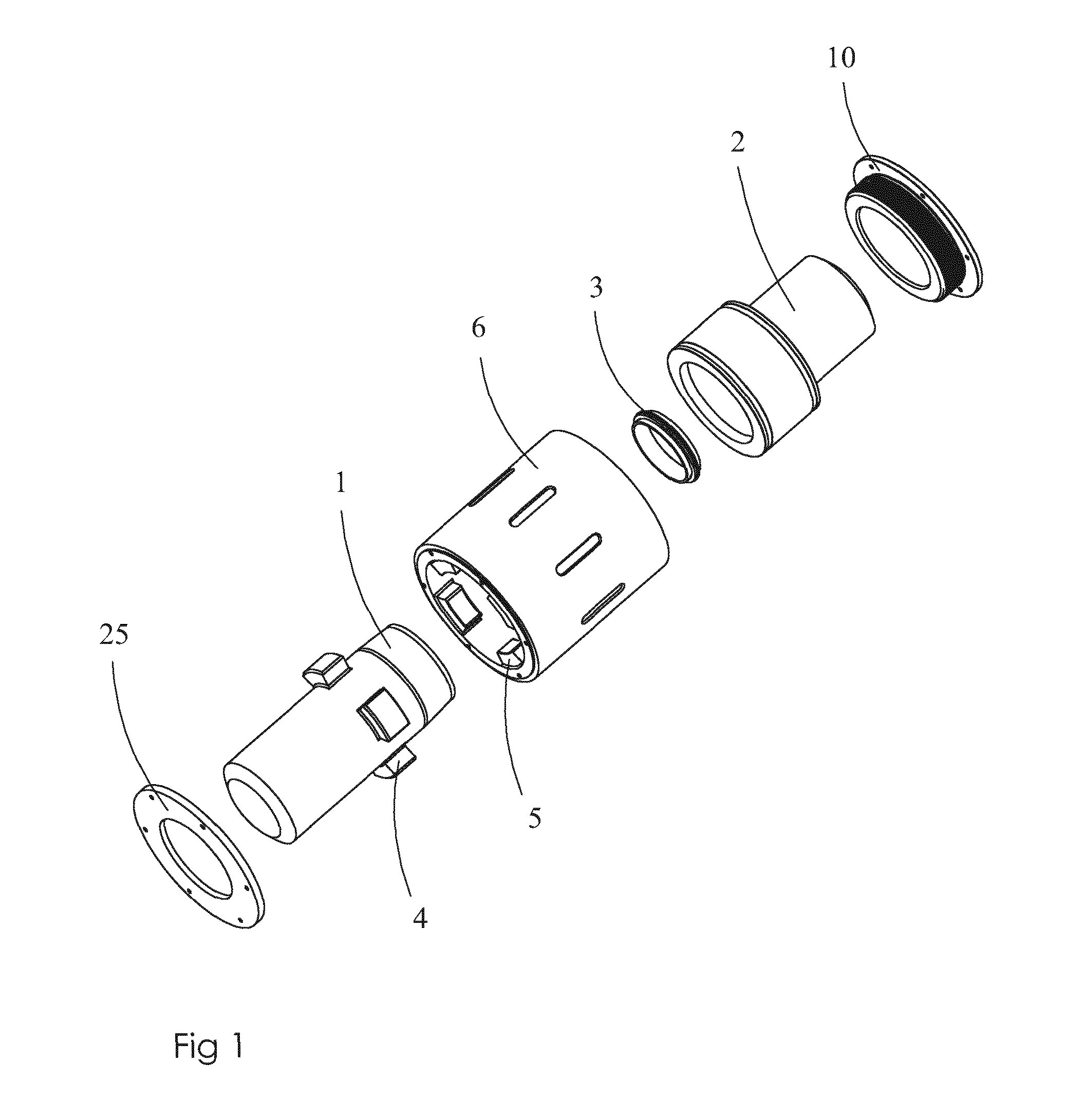
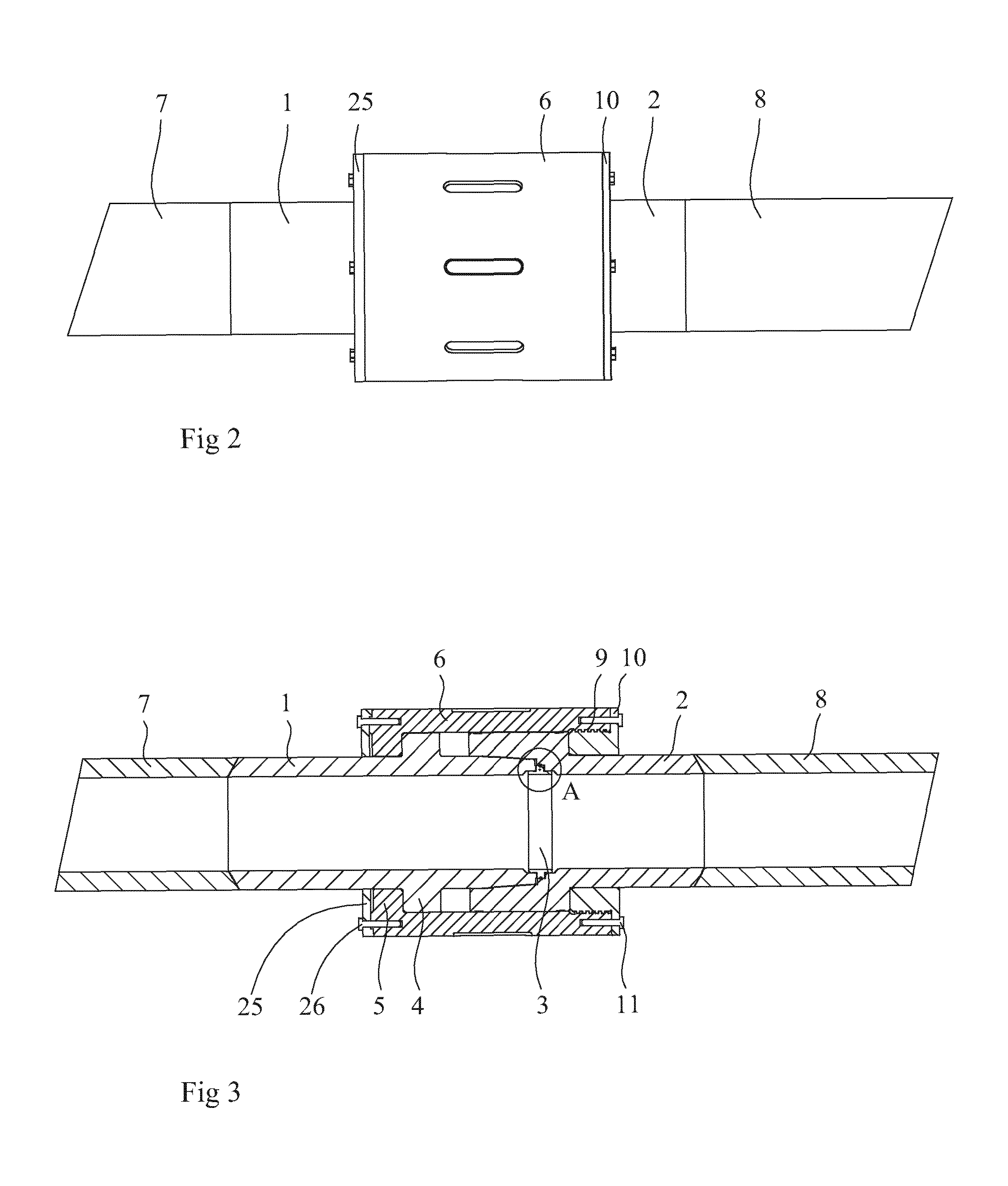
[0034]FIGS. 1-5 show a pipe coupling according to the invention. The pipe coupling comprises a first tubular element 1, a second tubular element 2, and an annular sealing element 3. As can be seen in FIGS. 3-5, which show the pipe coupling in assembled state, the sealing element is provided between and overlaps opposing ends of the first and the second tubular elements 1, 2 when being arranged in its operative position. There are also provided engagement members 4, 5 for engaging and interlocking the first tubular element 1 with the second tubular element 2. The engagement members 4, 5 are arranged so as to function as a bayonet coupling between the first tubular element 1 and the second tubular element 2. With reference to the figures it can be seen that in the particular embodiment presented here, there is provided a sleeve 6 which is attached to the second tubular element 2 and which carries the engagement members 5 associated to that specific tubular element. The bayonet couplin...


PUM


Abstract

A pipe coupling includes a first and second connected tubular element forming an elongated tube and being connected by a connection arrangement that biases the first tubular element against the second tubular. An annular sealing element is provided between and overlapping opposed end portions of the elements. The annular sealing element has a generally T-shaped cross-section and includes a first portion that forms a stem of the T-shaped cross section and extends in a radial direction and defines the outer periphery thereof, and a second portion formed by two opposing flanges that form the cross-bar of the T-shaped cross section and define the inner periphery thereof. At least one of the flanges presents a rounded bulge forming an outer peripheral surface of one flange. The bulge is sealed with an inner periphery of one of the tubular elements and extends continuously around the circumference of the annular sealing element.

Description

TECHNICAL FIELD[0001]The present invention relates to a pipe coupling comprising[0002]a first tubular element and a second tubular element connected to the first tubular element and forming an elongated tube therewith, wherein the first tubular element is connected to the second tubular element by a connection arrangement that permits a biasing of the first tubular element in relation to the second tubular element within a predetermined angular range, and said coupling further comprising[0003]an annular sealing element which is provided between and overlaps opposing end portions of the first and the second tubular elements, wherein the annular sealing element has a generally T-shaped cross-section,[0004]said sealing element comprising a first portion that forms a stem of said T-shaped cross section and extends in a radial direction of the sealing element and defines the outer periphery thereof, and[0005]a second portion formed by two opposing flanges that form the cross-bar of the T...

Claims


Application Information

Patent Timeline
IPC IPC(8): F16L23/18
CPCE21B17/046E21B17/085F16L37/252F16L27/073F16L23/18
Inventor JANSSON, TOMASTYLDHED, ERIK
Owner IKM GRUPPEN AS
Why Eureka
Try Eureka