Enclosure system for an antenna

a technology of enclosure system and antenna, which is applied in the direction of antennas, radiating element housings, electrical devices, etc., can solve the problems of increased cost, rigid materials, and high cost of exposed dish and any exposed components, so as to reduce the cost of the system, improve performance, and improve the effect of rf permeability

Inactive Publication Date: 2013-08-15
WINEGARD
View PDF3 Cites 25 Cited by
  • Summary
  • Abstract
  • Description
  • Claims
  • Application Information

AI Technical Summary

Benefits of technology

[0010]In the embodiments for a satellite dish antenna, the rim portion of the dish-shaped reflector is preferably covered and the covered reflector becomes part of the protective housing or enclosure. As compared to a typical radome design in which the entire dome of the radome must be made of expensive, radio frequency (RF) permeable material, only the cover over or across the rim portion of the dish-shaped reflector must then be made of such material. This is the case because in the present design, the dish-shaped reflector is fixed to and moves with the housing or enclosure in contrast to the typical radome design in which the dish-shaped reflector moves within and relative to the radome. The present design greatly reduces the cost of the system and even offers the user the option of making the cover out of more expensive and superior RF permeable material at less than or at least no additional, overall cost beyond a typical radome design made entirely of an inferior RF permeable material. That is, the cover can be made of the more expensive, better performing material and the rest of the housing of a much cheaper material as the dish-shaped reflector only receives signals through the cover and no other part of the protective housing as is the case in a typical radome. The result can be not only is a better performing antenna but also a less expensive one. Additionally, the design of the present invention with or without the cover also allows the rest of the enclosure to be made out of non-radio frequency permeable materi

Problems solved by technology

A disadvantage of enclosure systems with radomes is that the height of the radome is essentially a function of the size of the dish or reflector.
This high profile can present problems for example if the enclosure system with the radome is mounted on a recreational or similar vehicle and the vehicle is to be stored in a garage or under a protective structure with a height restriction.
Similarly, the high profile can present height problems for storage even if the enc

Method used


Image

  • Enclosure system for an antenna
  • Enclosure system for an antenna
  • Enclosure system for an antenna

Examples


Embodiment Construction

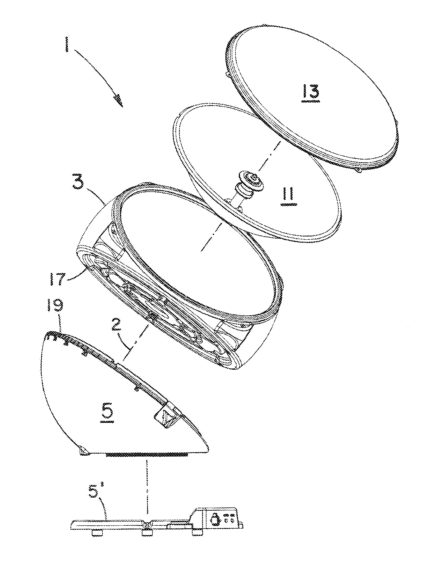
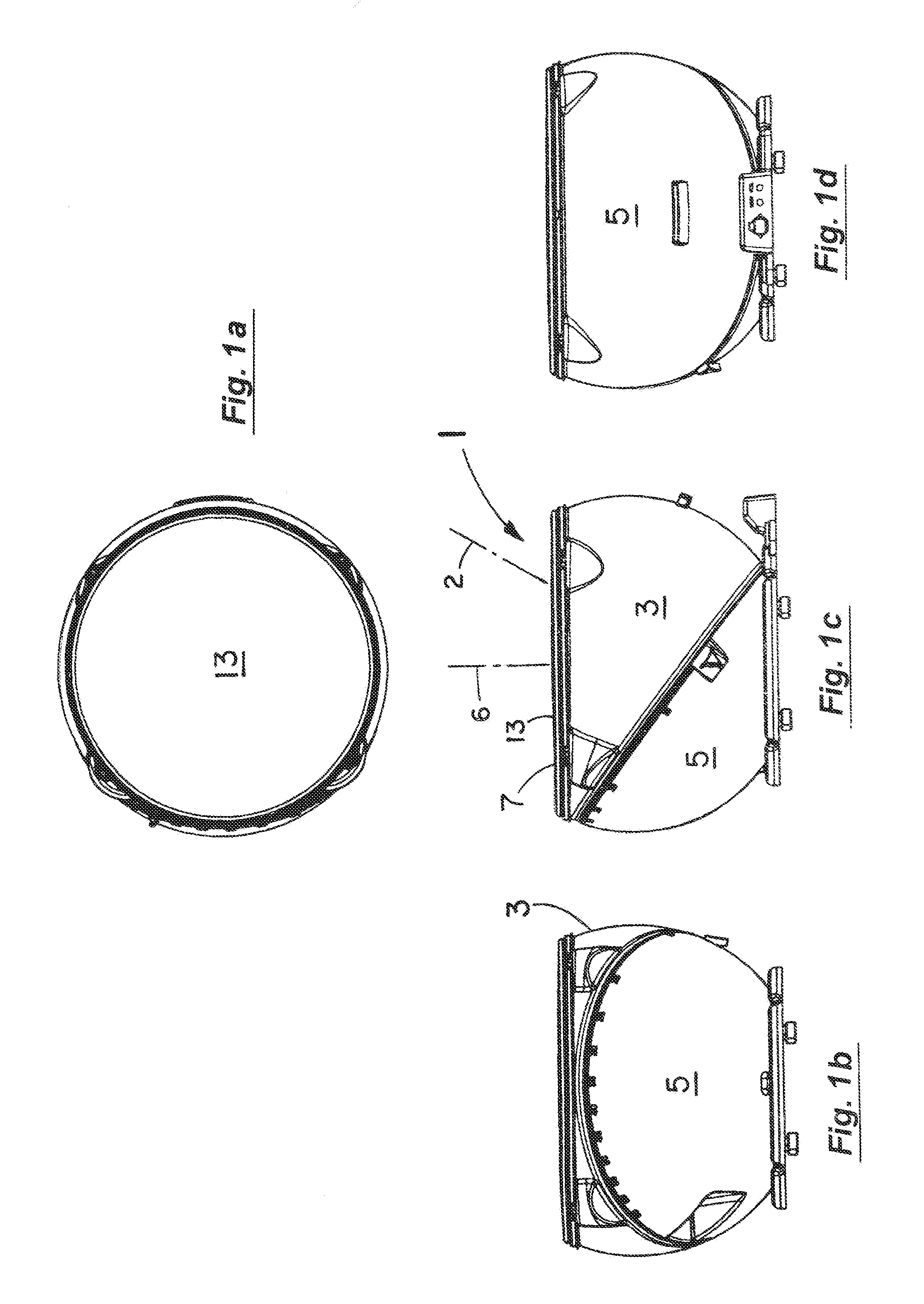
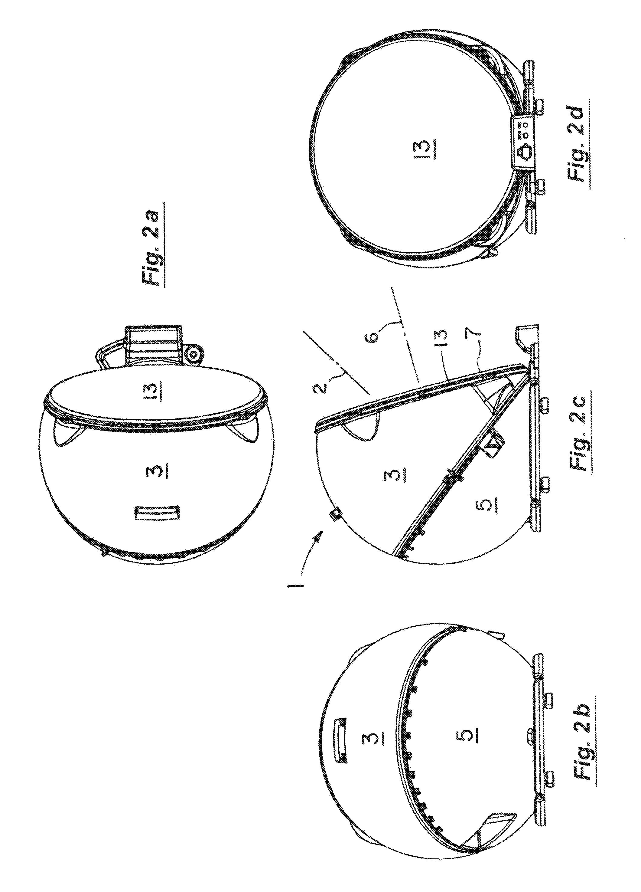
[0023]As shown in the series of views of FIGS. 1a-1d, the enclosure system 1 of this embodiment of the present invention includes an upper or elevation housing portion 3 (FIG. 1c) that is rotatably mounted to a lower or azimuth housing portion 5. In the position of FIG. 1c, the planar section 7 of the upper housing portion 3 is oriented substantially horizontally. In doing so and as explained in more detail below, the antenna element within the upper housing 3 (e.g., a dish-shaped reflector) is pointed upwardly at substantially 90 degrees to the horizontal. As indicated above, the upper housing portion 3 is rotatably mounted to the lower housing portion 5 and can be rotated about the axis 2 to the other extreme position of the series of views of FIG. 2a-2d. In the position of FIG. 2c, the planar section 7 of the upper housing portion 3 in this embodiment is nearly vertical with the antenna element in it pointing nearly horizontally. The further series of views of FIG. 3a-3e then sho...


PUM


Abstract

An enclosure system for antennas including satellite dish antennas and single frequency, narrowband and broadband ones. The system includes at least upper and lower housing portions mounted to each other for rotational movement about a first axis inclined to the vertical. The portions have respective, peripheral sections extending about the first axis and substantially perpendicular to the inclined, first axis. The satellite antenna dish is mounted to the upper housing portion to extend substantially about a second axis substantially intersecting the first axis at an inclined angle. The upper housing portion can be rotated about the inclined, first axis relative to the lower housing portion wherein the second axis of the dish essentially forms or defines a cone about the first axis to position the plane of the dish rim portion in any of a plurality of orientations essentially between a substantially horizontal one and a substantially vertical one.

Description

RELATED APPLICATIONS[0001]This application claims the benefit of U.S. Provisional Patent Application Ser. No. 61 / 597,147 filed Feb. 9, 2012, which is incorporated herein by reference.BACKGROUND OF THE INVENTION[0002]1. Field of the Invention[0003]This invention relates to the field of enclosure systems for antennas including satellite dish, single frequency, narrowband frequency, and broadband frequency ones.[0004]2. Discussion of the Background[0005]Enclosure systems for antennas have been designed that offer a wide variety of advantages and disadvantages. For satellite dish antennas in particular, systems with radomes are a well known option that cover or enclose the dish and its components (e.g., amplifier and motorized drive). In doing so, radomes offer the distinct, cost-saving advantage that less expensive and lower performing components can be used because the antenna and its components are protected from the elements under the radome. As for example and since the electronics...

Claims


Application Information

Patent Timeline
IPC IPC(8): H01Q19/12
CPCH01Q1/42H01Q19/12
Inventor VENGHAUS, BRENT LEELANZ, ORRIN RYAN
Owner WINEGARD
Why Eureka
Try Eureka