
Exposure Value Adjustment Apparatus, Method, and Non-Transitory Tangible Machine-Readable Medium Thereof

a value adjustment and exposure value technology, applied in the field of exposure value adjustment apparatus, method, and non-transitory computer readable medium, can solve the problems of inability to recover enough highlights and/or overexposure values, and conventional hdr techniques have no knowledge of how much under-exposure value to recover enough highlights and/or over-exposure values, etc., to achieve high dynamic range (hdr)

Active Publication Date: 2013-08-15
HTC CORP
View PDF4 Cites 13 Cited by
  • Summary
  • Abstract
  • Description
  • Claims
  • Application Information

AI Technical Summary

Benefits of technology

The present invention is a technique that uses a reference image to determine the exposure condition of an image. By analyzing the histogram of the reference image, the invention decides on a low, middle, and high exposure value for the image. This results in images that have more detail, and a high dynamic range (HDR) image can be generated based on these details. In simple terms, this technique helps to capture more detail in an image.

Problems solved by technology

These conventional HDR techniques have drawbacks because environment conditions have not been considered.
Specifically, conventional HDR techniques have no knowledge of how much under-expose value to recover enough highlights and / or how much the over-expose value to recover enough shadows.
However, this is often not the case in our real life.
For example, when the current image is under-exposed, a setting of −2 EV will only complicate the problem.
Likewise, when the current image is over-exposed, a setting of +2 EV will complicate the problem as well.
Consequently, the technique for generating HDR images that takes the environment conditions into consideration is still in an urgent need.

Method used


Image

  • Exposure Value Adjustment Apparatus, Method, and Non-Transitory Tangible Machine-Readable Medium Thereof
  • Exposure Value Adjustment Apparatus, Method, and Non-Transitory Tangible Machine-Readable Medium Thereof
  • Exposure Value Adjustment Apparatus, Method, and Non-Transitory Tangible Machine-Readable Medium Thereof

Examples


first embodiment

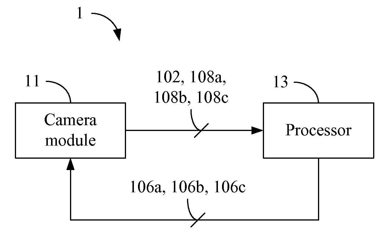
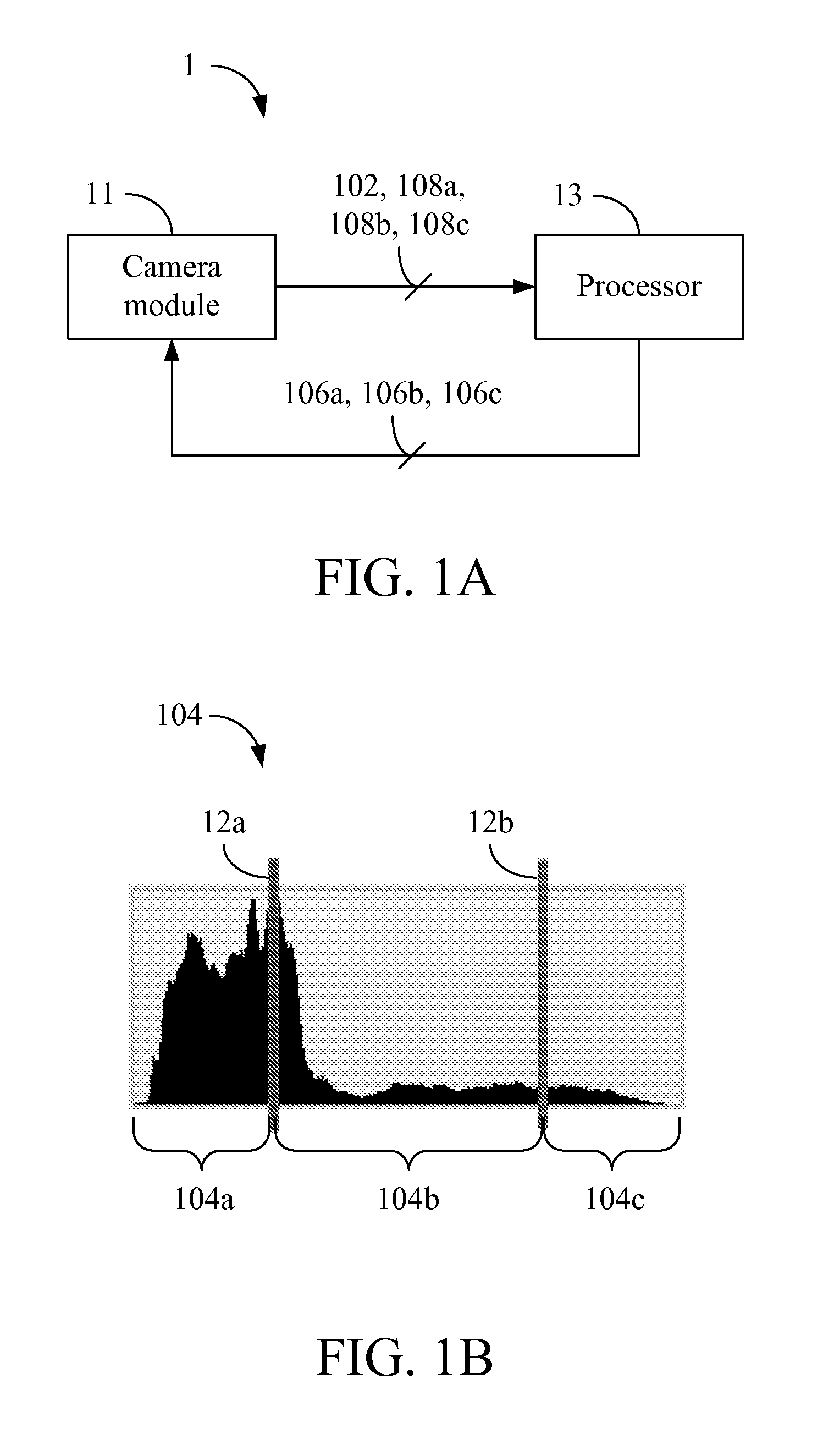
[0025]the present invention is an exposure value adjustment apparatus 1 and a schematic view of which is depicted in FIG. 1A. The exposure value adjustment apparatus 1 comprises a camera module 11 and a processor 13, wherein the camera module 11 and the processor 13 electrically connected to each other. The processor 13 may be any of various processors, central processing units (CPUs), microprocessors, or other computing devices that are well-known by those of ordinary skill in the art.

[0026]In this embodiment, the camera module 11 captures a reference image 102 by a base exposure value. The reference image 102 may be a preview image and the base exposure value may be 0 EV. The processor 13 then generates a histogram 104 of the reference image 102 as shown in FIG. 1B. Next, the processor 13 divides the histogram 104 into a low partial histogram 104a, a middle partial histogram 104b, and a high partial histogram 104c by a first threshold 12a and a second threshold 12b. It is noted th...

second embodiment

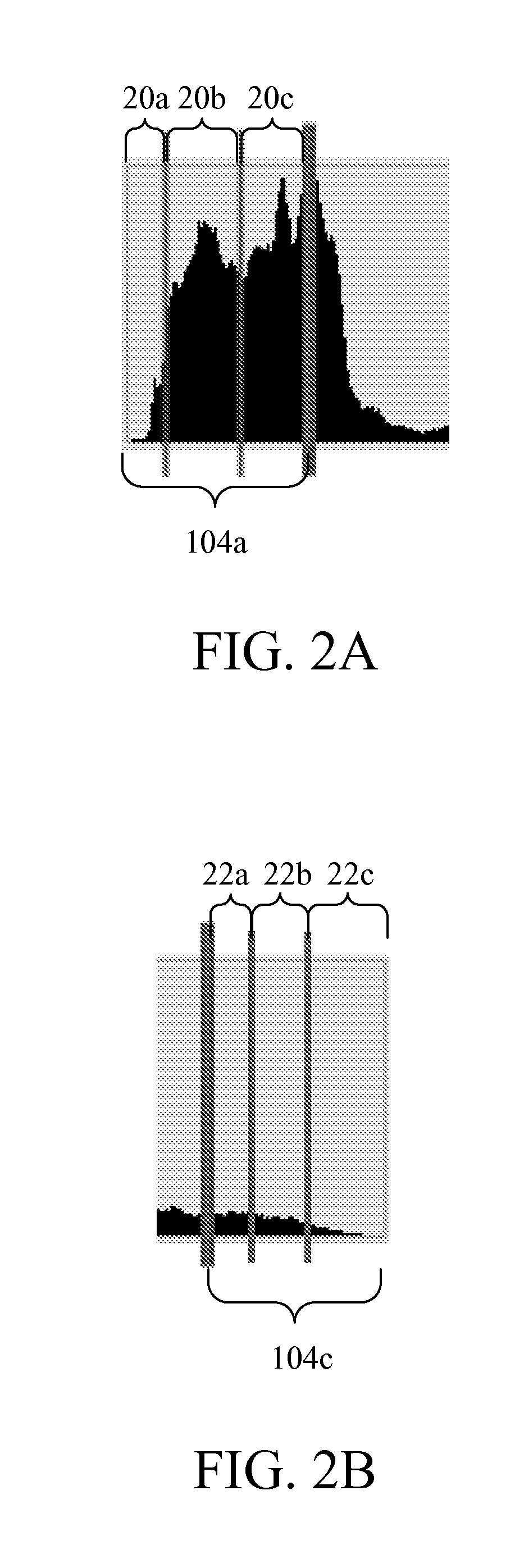
[0036]From the above descriptions, it is learned that the second embodiment determines whether the reference image 102 was taken under-exposed and / or over-exposed more specifically. In addition, the low partial histogram 104a is divided into portions 20a, 20b, 20c that correspond to various exposure values greater than the base exposure value, so the high exposure value 106c can be determined more accurately by considering the luminance distribution of the pixel in the low partial histogram 104a. Likewise, the high partial histogram 104c is divided into portions 22a, 22b, 22c that correspond to various exposure values smaller than the base exposure value, so the low exposure value 106a can be determined more accurately by considering the luminance distribution of the pixel in the high partial histogram 104c. As the low exposure value 106a, the middle exposure value 106b, and the high exposure value 106c are decided more accurately, the resultant HDR image contains more details.

[0037...

third embodiment

[0038]In the third embodiment, the low exposure value 106a and the high exposure value 106c will be further fine-tuned before being used for deciding the middle exposure value 106b. Specifically, the processor 13 further determines whether the high exposure value 106c is greater than a predetermined exposure value. In other words, the processor 13 determines whether the backlight is strong and / or whether the main object in the reference image 102 is dark. If the high exposure value 106c is greater than the predetermined exposure value, it means that the backlight is strong and / or the main object in the reference image 102. Thus, the processor 13 increases the high exposure value 106c by a predetermined value, such as increasing the high exposure value 106c by +0.5 EV.

[0039]In addition, the processor 13 determines whether an average luminance value of the reference image 102 is smaller than a predetermined luminance value. That is, the processor 13 determines whether the environment ...


PUM


Abstract

An exposure value adjustment apparatus, method, and non-transitory tangible machine-readable medium thereof are provided. The exposure value adjustment apparatus includes a camera module and a processor. The camera module captures a reference image by a base exposure value. The processor generates a histogram of the reference image, divides the histogram into a low partial histogram, a middle partial histogram, and a high partial histogram by a first threshold and a second threshold, decides a high exposure value according to the low partial histogram and the middle partial histogram, decides a low exposure value according to the high partial histogram and the middle partial histogram, and decides a middle exposure value according to the high exposure value and the low exposure value. The low exposure value is lower than the high exposure value, and the middle exposure value is between the high exposure value and the low exposure value.

Description

[0001]This application claims the benefit of U.S. Provisional Application Ser. No. 61 / 597,845 filed on Feb. 13, 2012 and U.S. Provisional Application Ser. No. 61 / 602,648 filed on Feb. 24, 2012.CROSS-REFERENCES TO RELATED APPLICATIONS[0002]Not applicable.BACKGROUND OF THE INVENTION[0003]1. Field of the Invention[0004]The present invention relates to an exposure value adjustment apparatus, method, and non-transitory computer readable medium thereof; more specifically, the present invention relates to an exposure value adjustment apparatus, method, and non-transitory computer readable medium that utilizes the histogram of a reference image.[0005]2. Descriptions of the Related Art[0006]The techniques for generating High Dynamic Range (HDR) images have been investigated in recent years, which allow an image to have a greater dynamic range between the lightest and darkest areas of the image.[0007]Conventional HDR techniques capture several images (e.g. three images) by different exposure ...

Claims


Application Information

Patent Timeline
Patent Type & Authority Applications(United States)
IPC IPC(8): H04N5/235G06T5/40H04N23/76
CPCG06T5/40H04N5/235G06T5/009G06T2207/20221G06T2200/21G06T2207/10016G06T2207/20008G06T5/50H04N23/70G06T5/92
Inventor LIN, CHIA YEN MICHAELWU, JING-LUNGCHUEH, HSIN-TIHSU, YU-CHENGYANG, HUNG-CHIHHSU, LI-CHUN
Owner HTC CORP
Learn More