

Fixed structure for liquid crystal display device and liquid crystal display device thereof
- Summary
- Abstract
- Description
- Claims
- Application Information
AI Technical Summary
Benefits of technology
Problems solved by technology
Method used
Image

Examples
Embodiment Construction
[0031]The technical method for realizing the purpose of the invention will be exactly illustrated according to the attached drawings and the exemplary embodiments. It should be understood that the described detailed exemplary embodiment is only used for illustrating this invention rather than limiting.
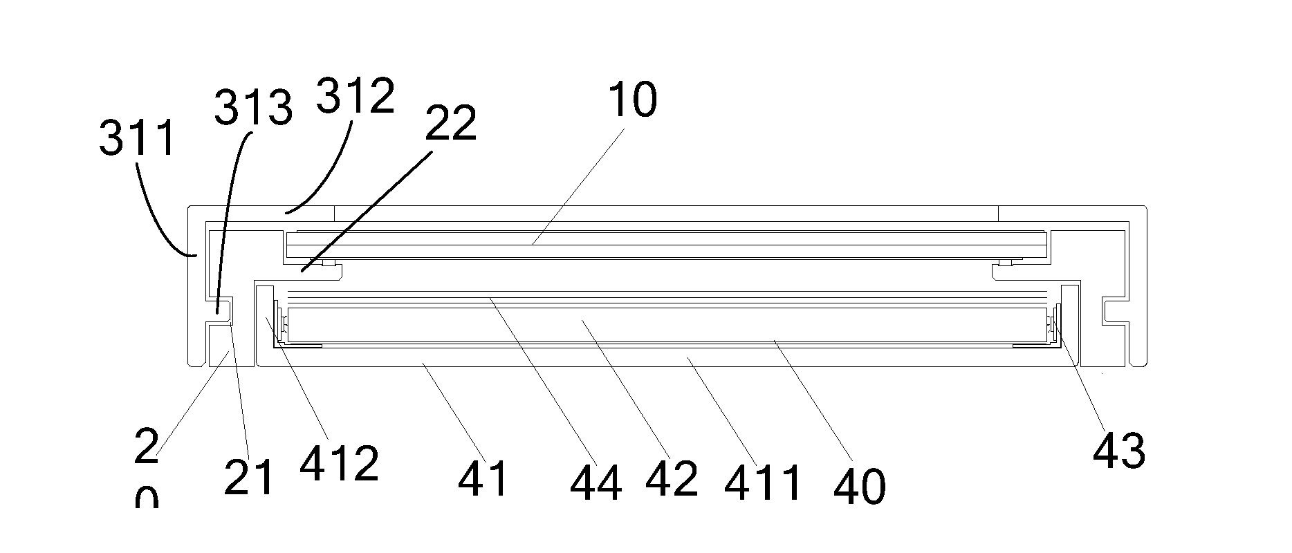
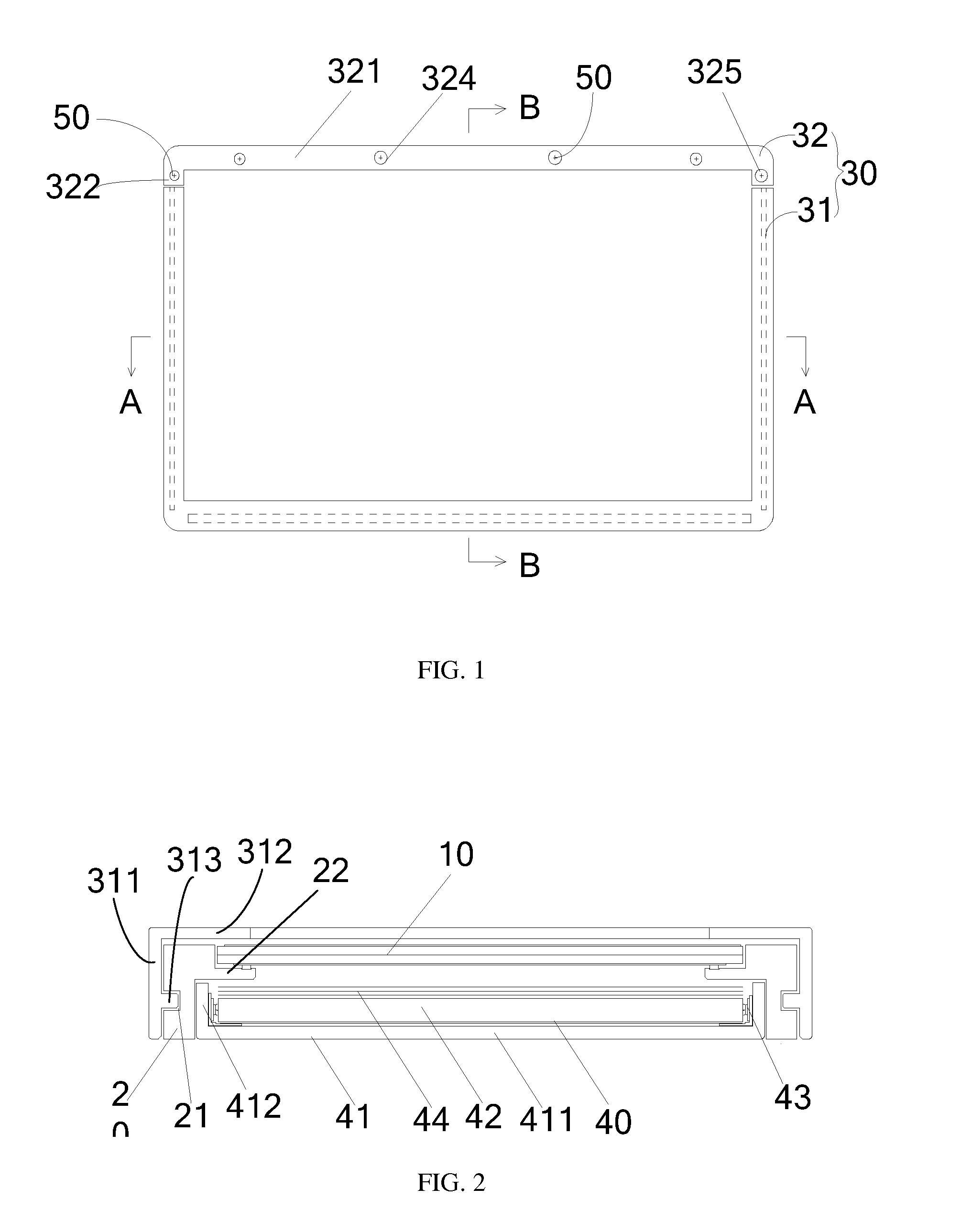
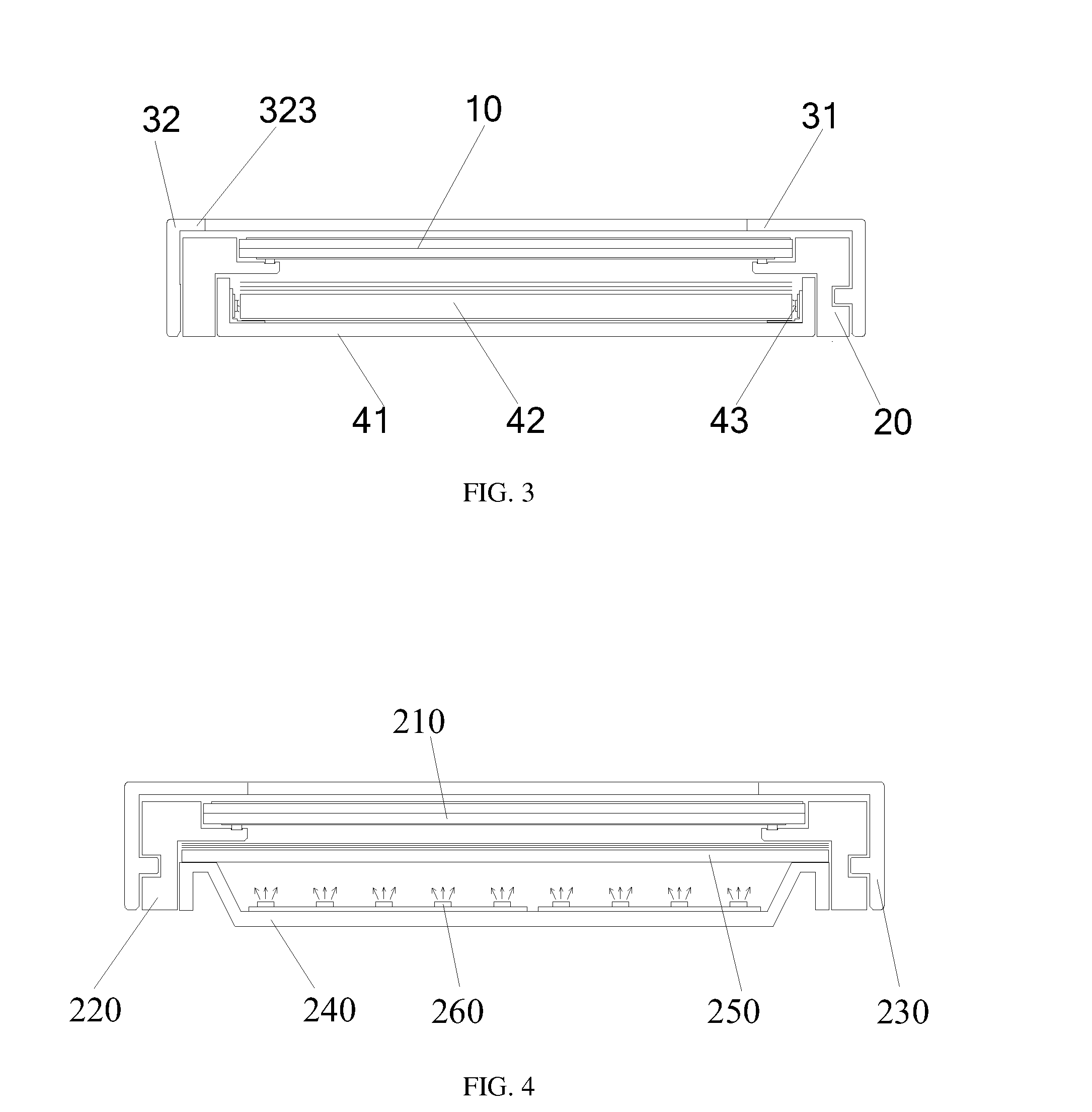
[0032]Please take the FIG. 1, FIG. 2 and FIG. 3 as references, wherein FIG. 1 is the front view for the first exemplary embodiment of the liquid display device in the invention; FIG. 2 is the cutaway view in A-A direction illustrated in FIG. 1; and FIG. 3 is the cutaway view in B-B direction illustrated in FIG. 1.
[0033]In this exemplary embodiment, said liquid crystal display device includes a liquid crystal panel 10, a main-body rubber frame 20, a front frame 30 and a backlight module 40. In this exemplary embodiment, said backlight module 40 is a side-light type backlight module, which includes a back panel 41, a light guide plate 42, a light source 43 and an optical membrane unit 44...
PUM
 Abstract
Description
Claims
Application Information