Patella Resection Instrument Guide Having Optional Patient-Specific Features

a technology of instrument guide and patella, which is applied in the field of patella resection instrument guide, can solve the problems of reduced joint flexion, limited options for surgeons to resurface the underside of the patella, and inability to restore the knee to its normal function, and achieves the effect of convenient one-handed operation of the clamp

Inactive Publication Date: 2013-08-15
CONFORMIS
View PDF3 Cites 100 Cited by
  • Summary
  • Abstract
  • Description
  • Claims
  • Application Information

AI Technical Summary

Benefits of technology

[0013]If desired, the various component surface features could be designed to accommodate concentric or cylindrical patellas, oblong / obround patellas or non-cylindrical patellas. Each of the patellar head engagement systems could optionally contain patellar cut / drill guides or other visible and / or tactile features to assist the surgeon in accurately resecting the patella.
[0015]In various preferred embodiments, the patella clamp will include features that desirably facilitate the one-handed operation of the clamp by the surgeon, thereby allowing the surgeon to hold and / or manipulate the patient anatomy with a first hand, while placing and securing the clamp proximate to the anatomy with the other. Desirably the entire patellar clamp assembly and associated components are easily useable by a single operator, i.e., the surgeon.

Problems solved by technology

Traditionally, however, surgeons have been faced with limited options to resurface the underside of the patella and measure the height of the patella.
If a surgeon elects to “free hand” a resection of the patella, there may be various complications that arise due to the impreciseness of the cut, which can include a resulting inability to restore the knee to its normal function.
In many cases, a miscalculation or other unsuccessful outcome of any of these steps may lead to under-resection, over-resection or oblique undesired cuts to the patella surfaces, causing decreased joint flexion, early implant wear, patellar fracture (i.e., the patella is too thin), instability of the knee, misalignment of the knee resulting in considerably increased forces across the tibio-femoral joint, migration of the implant, improper patellar tracking, and possible failure to alleviate and / or return of knee joint pain.
Even where modular instrument kits may be provided to assist with patellar resection and / or preparation, a variety of the aforementioned issues and complications can still exist.
The sheer number of components involved in such a kit, along with the host of potential tool choices and combinations thereof, significantly increases the amount of back-table space required to accommodate the surgical kit(s), as well as significantly increases the surgeon's difficulty in selecting and / or employing the proper size and shape of instrument.
Moreover, even in systems incorporating numerous modular components, the surgeon will still be forced to choose components and / or component combinations that approximate a desired shape and / or size of the target anatomy, and such inaccuracies can result in similar unsuccessful outcomes as those described above.
Moreover, additional limitations of modular kits can include (1) a requirement for significant training of surgeons for use of kits involving a significant number of kit pieces and / or component combinations, (2) the opportunity for multi-piece kits to be missing components or other kit pieces that may be improperly shipped to the hospital or other locations, (3) the kit pieces may have improper sizes available, or such pieces may be improperly toleranced, (4) the kit(s) may require significant storage and sterilization resources, and often involve significant “real estate” in the operating room as well as multiple persons to assemble or assist with the surgeon's conduct of the procedure, (5) particularized training and / or skills of the scrub technician may be required, which may limit available personnel for assisting with the surgical procedure, (6) kits may not account for unusual anatomical features, including non-standard and / or unusual patellar shape and / or size, and (7) such kits and the procedures they mandate can significantly increase both preoperative and operative planning and surgical execution time.

Method used


Image

  • Patella Resection Instrument Guide Having Optional Patient-Specific Features
  • Patella Resection Instrument Guide Having Optional Patient-Specific Features
  • Patella Resection Instrument Guide Having Optional Patient-Specific Features

Examples


Embodiment Construction

[0070]Imaging Techniques

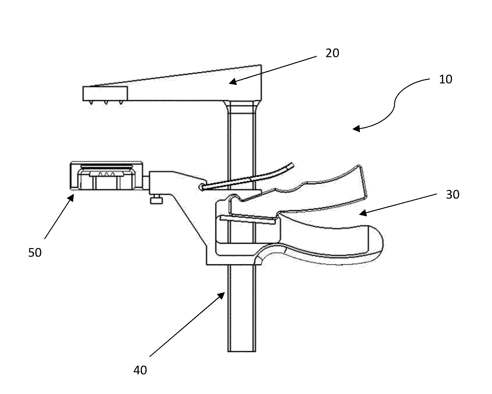
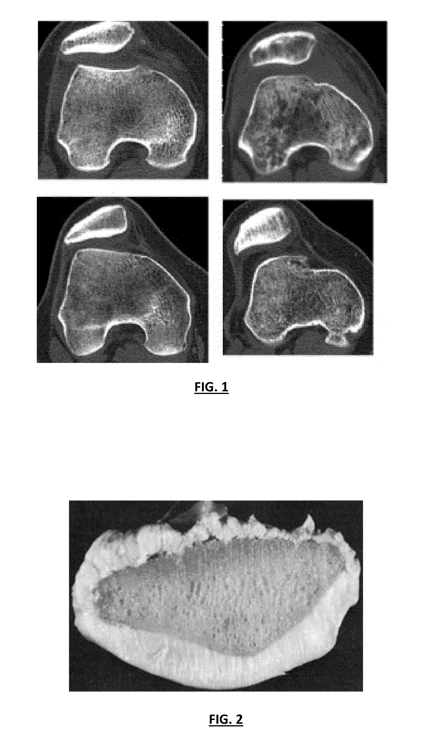
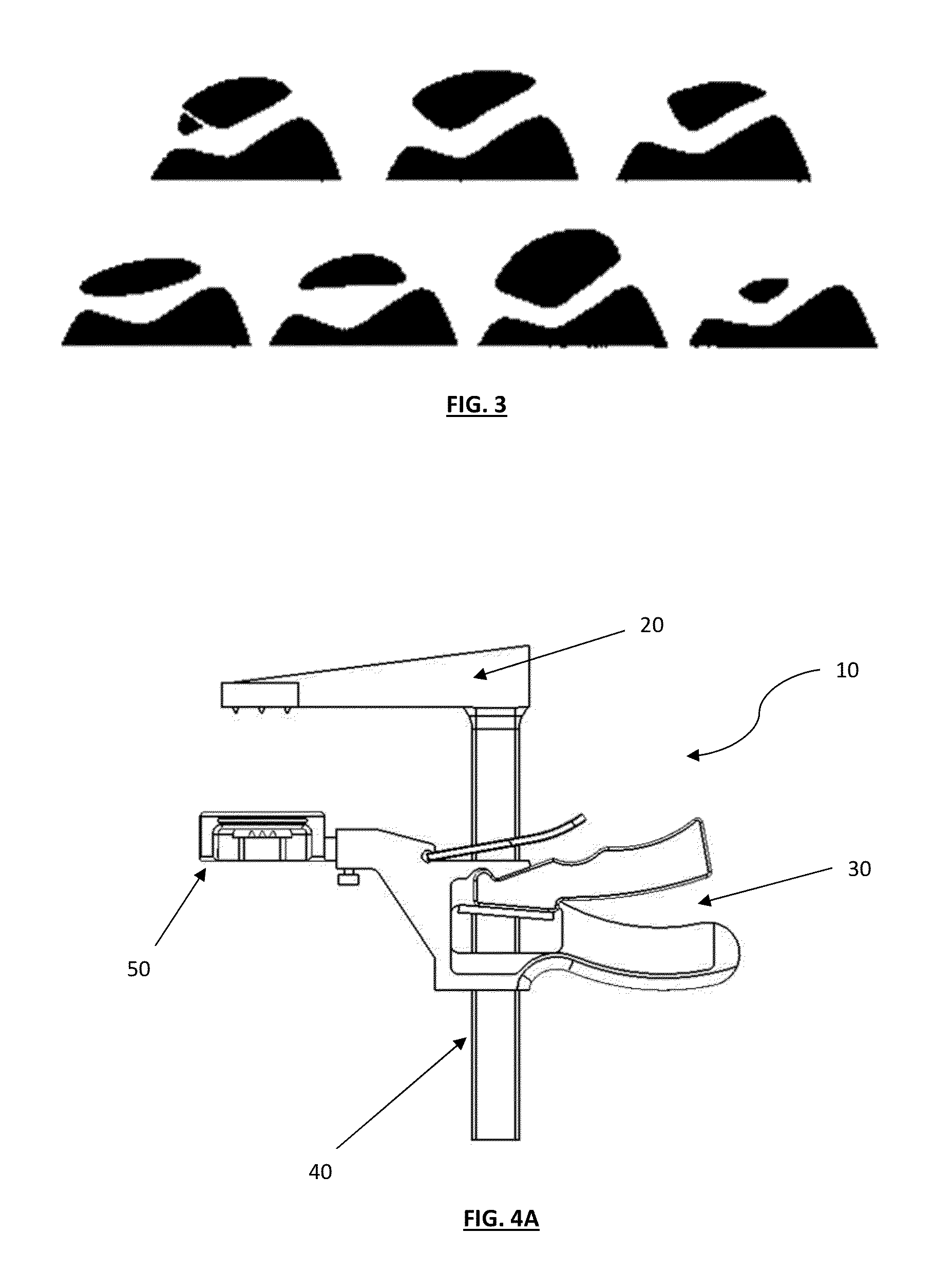
[0071]Various features of the present invention may include the employment of a variety of imaging techniques that are suitable for measuring thickness, size, area, volume, width, perimeter and / or surface contours of the diseased patella. Such imaging techniques may be desirable to recreate natural or substantially similar natural surfaces and / or electronic image data thereof, facilitating the design and / or derivation of the specific patellar assembly to repair or replace the patella during surgery. Using the proper patellar assembly with specifically designed shaped and / or contoured patellar heads may significantly improve alignment of the tool and / or other surgical tools, thereby improving alignment of patellar features with the articular or implant surfaces and resulting joint congruity because of more accurate resection and placement of the patellar button. Poor alignment and poor joint congruity can, for example, lead to instability of the joint. In the ...


PUM


Abstract

Disclosed are improved and / or patient-adapted (e.g., patient-specific and / or patient-engineered) patellar clamp systems, surgical methods and related surgical tools. The various clamp assemblies can facilitate one-handed operation by a user and can include modular features that provide for ease of interchangeability to accommodate components having patient specific features that conform or substantially conform to the patient's patellar anatomy.

Description

RELATED APPLICATIONS[0001]This application claims the benefit of U.S. Provisional Patent Application Ser. No. 61 / 596,222, entitled “Patella Resection Instrument Guide Having Optional Patient-Specific Features”, filed Feb. 7, 2012, from which priority is claimed under 35 U.S.C. 119, and the disclosure of which is hereby incorporated herein by reference in its entirety.TECHNICAL FIELD[0002]The invention relates to improved and / or patient-adapted (e.g., patient-specific and / or patient-engineered) patellar clamp systems and related surgical tools.BACKGROUND OF THE INVENTION[0003]When a patient's knee is severely damaged, such as by osteoarthritis, rheumatoid arthritis, or post-traumatic arthritis, it may be desirous to repair and / or replace portions or the entirety of the knee with a total or partial knee replacement implant, which may include the total or partial patellar resurfacing or partial / total excision of the patella. Knee replacement surgery is a well-tolerated and highly succe...

Claims


Application Information

Patent Timeline
Patent Type & Authority Applications(United States)
IPC IPC(8): A61B17/17
CPCA61B17/1767A61B17/158
Inventor LANDES, MARK D.WONG, TERRANCEBERG, PAULA MARIEKURTZ, WILLIAMLANG, PHILIPP
Owner CONFORMIS
Why Eureka
Try Eureka