
Molding method for thin-wall plastic product

A molding method and product technology, applied in the direction of coating, etc., can solve the problems of increasing the difficulty of mold processing, affecting product quality, and product sticking, so as to reduce the difficulty of mold design, avoid excessive injection pressure, and facilitate glue removal and filling Effect

Inactive Publication Date: 2014-09-10
DONGGUAN GOOD MARK NEW PRECISION TECH CO LTD
View PDF5 Cites 5 Cited by
  • Summary
  • Abstract
  • Description
  • Claims
  • Application Information

AI Technical Summary

Problems solved by technology

[0002] In the molding process of thin-walled plastic products, in order to fully melt the melt and reduce the injection pressure, there are usually multiple plastic inlets on the thin-walled products. Inconsistency can easily lead to the formation of weld line defects on the surface of the product, affecting product quality. At the same time, multiple plastic inlets will also generate multiple gate waste, wasting plastic materials, and increasing the workload of gate removal; in addition , the design of multiple glue inlets will also increase the difficulty of mold processing, thereby increasing production costs
Therefore, in order to reduce the weld marks on the surface of the product and reduce the production cost, the number of glue inlets should be reduced as much as possible, but at the same time, fewer glue inlets will lead to excessive injection pressure, and excessive injection pressure will easily lead to product sticking and bending Deformation, top white, flash and other defects

Method used


Image

  • Molding method for thin-wall plastic product
  • Molding method for thin-wall plastic product

Examples


specific Embodiment

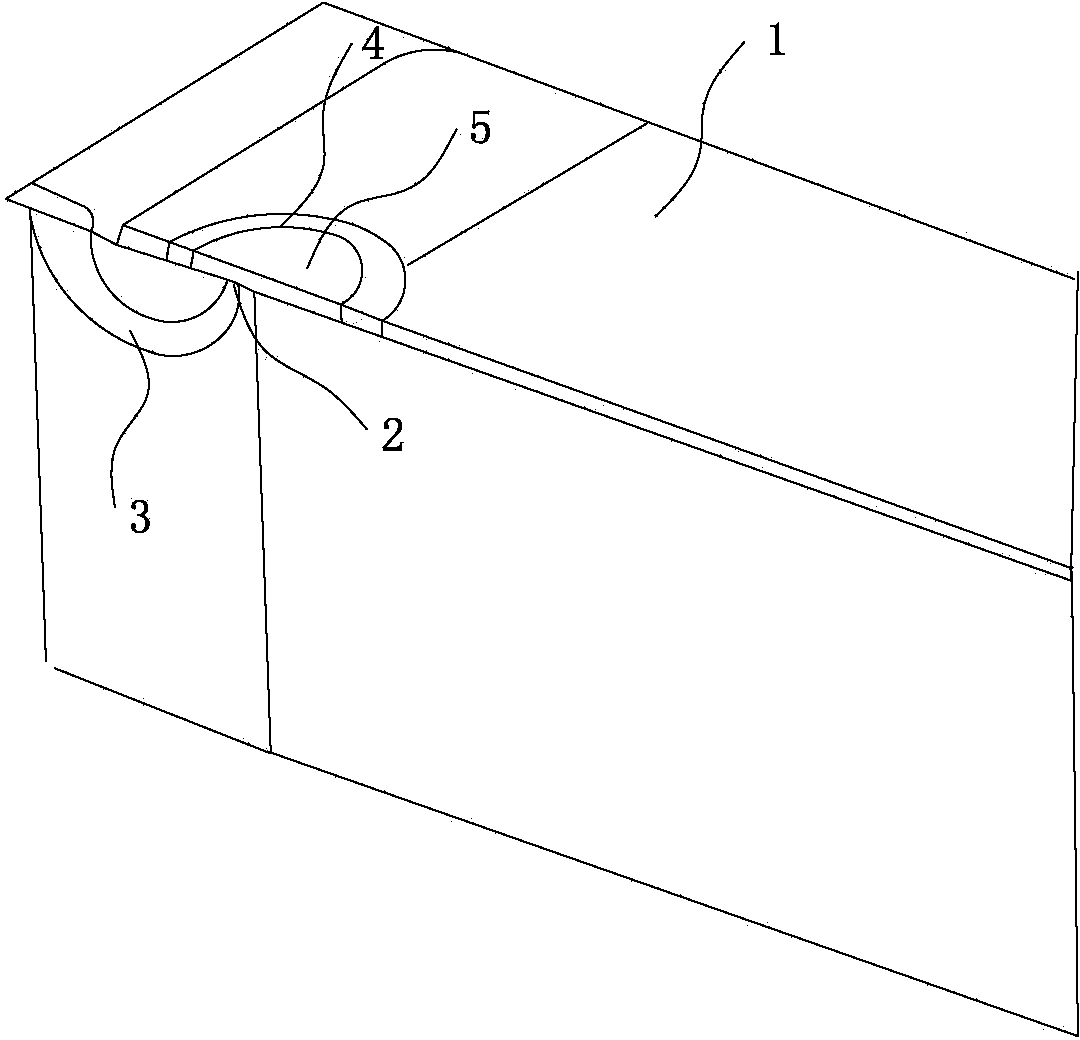
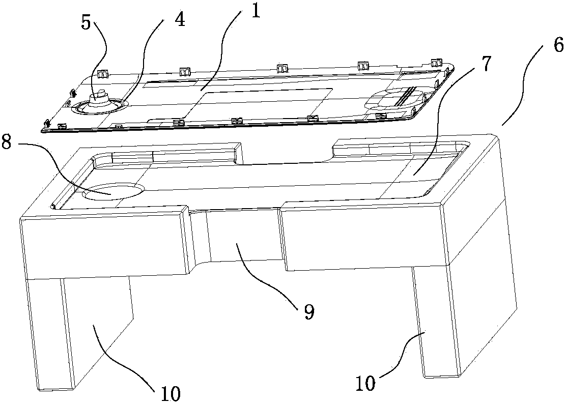
[0021] A specific embodiment of a molding method of a thin-walled plastic product of the present invention, the manufacturing method includes the following steps: injection molding of a thin-walled product 1, preferably, the thin-walled product 1 is a mobile phone back shell, and the mobile phone back shell is injection-molded The gating system used for molding, such as figure 1 As shown, it includes the use of a large nozzle type glue inlet for glue feeding, which facilitates the glue flow of the melt, and the glue inlet point 2 is a single glue inlet point 2, and the glue inlet point 2 is set in the functional hole 4 of the thin-walled product 1 Inside, the functional hole 4 belongs to a part of the thin-walled product after molding, and is a structure for realizing a certain function after the thin-walled product is formed. For example, the functional hole 4 is the camera hole on the back shell of the mobile phone. The larger the diameter, the glue inlet point 2 can be app...


PUM


Abstract

The invention provides a molding method for a thin-wall plastic product. The molding method comprises the following steps: injection molding of the thin-wall product, wherein a side gate type glue feeding point is used for feeding glue, the glue feeding point is a single glue feeding point, the glue feeding point is arranged inside a functional hole of the product, and a melt inside the functional hole of the thin-wall product forms a glue feeding position integrally with the thin-wall product after melt injection; and cutting of the glue feeding point, wherein the molded thin-wall product is fixedly arranged on a positioning jig; the glue feeding position inside the functional hole is removed by using a numerically-controlled machine tool. The molding method provided by the invention is convenient in sufficient glue-flowing and filling of the melt; weld marks generated on the surface of the product due to arrangement of the plurality of glue feeding points can be removed; the pressure of the injection molding can be prevented from being too large; meanwhile, the waste of materials and the design difficulty of the die can be reduced; the cost is reduced. Furthermore, a cutter controlled by the numerically-controlled machine tool can be used for cutting the glue feeding position positioned on the positioning jig from the functional hole rapidly and accurately, so that a qualified product can be obtained.

Description

technical field [0001] The invention relates to the technical field of forming thin-walled products, in particular to a method for forming thin-walled plastic products. Background technique [0002] In the molding process of thin-walled plastic products, in order to fully melt the melt and reduce the injection pressure, there are usually multiple plastic inlets on the thin-walled products. Inconsistency can easily lead to the formation of weld line defects on the surface of the product, affecting product quality. At the same time, multiple plastic inlets will also generate multiple gate waste, wasting plastic materials, and increasing the workload of gate removal; in addition , The design of multiple glue inlets will also increase the difficulty of mold processing, thereby increasing production costs. Therefore, in order to reduce the weld marks on the surface of the product and reduce the production cost, the number of glue inlets should be reduced as much as possible, but...

Claims


Application Information

Patent Timeline
IPC IPC(8): B29C45/00B29C45/27B29C45/38
CPCB29C45/0025B29C45/27B29C45/38B29C2045/0058
Inventor 陈荣陈冠何智安余晓初
Owner DONGGUAN GOOD MARK NEW PRECISION TECH CO LTD
Learn More