

Decorative joint filling device for decoration and using method thereof
A technology of beautifying seams and beautifying agents, applied in the direction of cleaning methods using tools, chemical instruments and methods, cleaning methods and utensils, etc., can solve the problem of poor bonding effect of beautifying agents, inconvenient cleaning of dust, and affecting the overall beauty Seam and other problems, to achieve the effect of improving the bonding effect, ensuring integrity, and ensuring the overall beautiful seam
- Summary
- Abstract
- Description
- Claims
- Application Information
AI Technical Summary
Problems solved by technology
Method used
Image

Examples
Embodiment 1
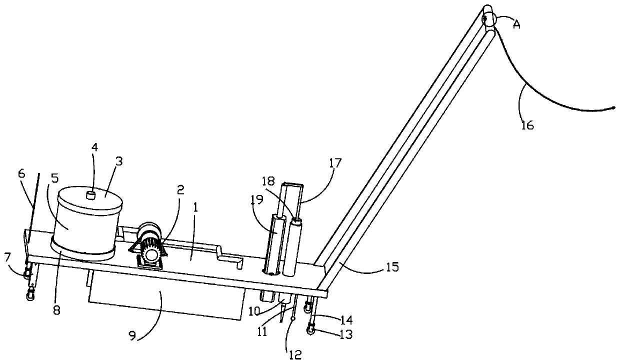
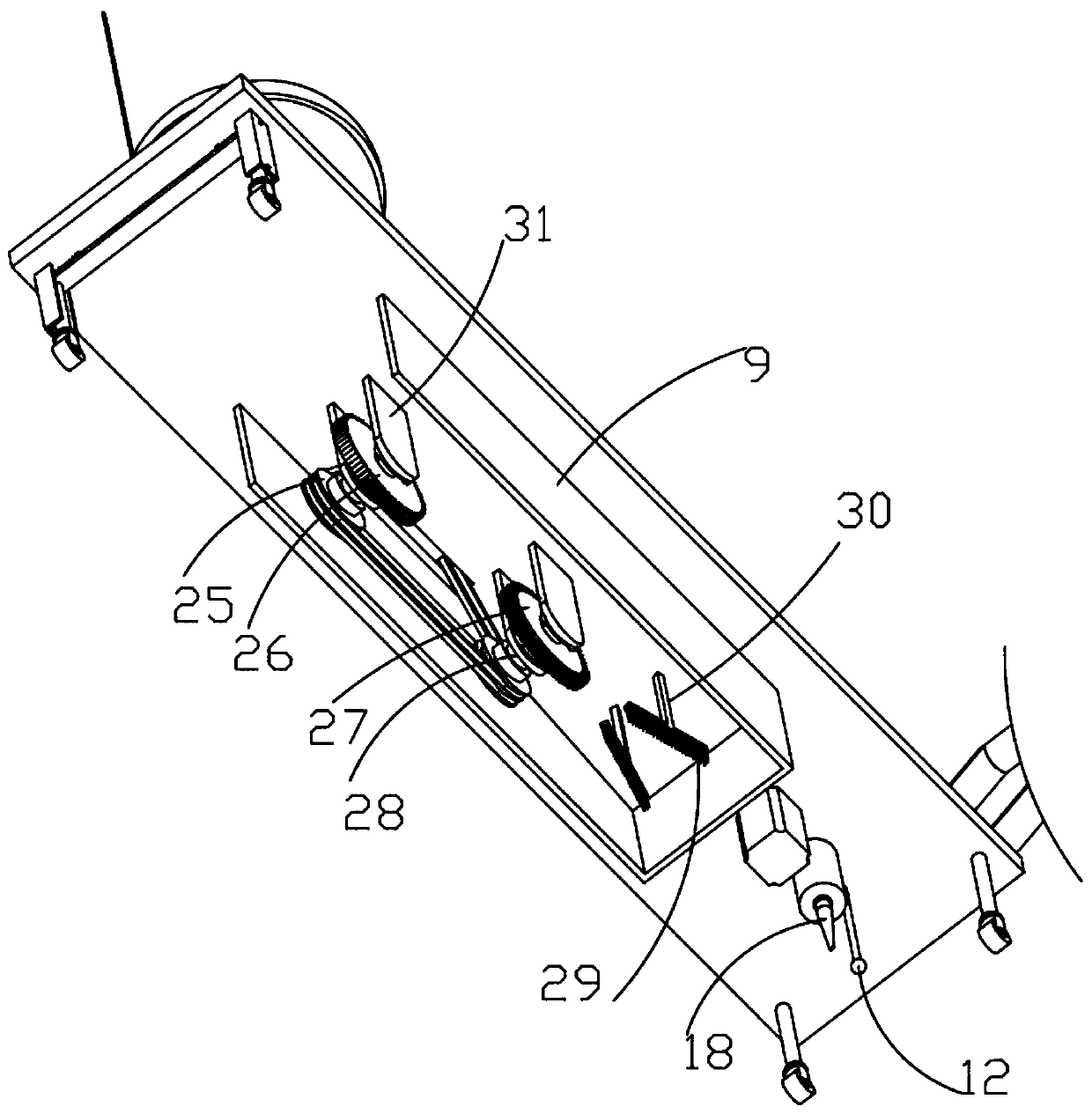
[0045] Such as Figure 1-8 A beautifying sewing device for decoration is shown, which includes a base plate 1, a drive motor 2 and an electric push rod 19, and is characterized in that: a U-shaped block 7 is symmetrically fixedly connected to the bottom of the left end of the base plate 1, and the outer wall of the U-shaped block 7 is symmetrically provided with The positioning hole 40, the U-shaped block 7 is fitted and slidably connected with a horizontal plate 39 through the chute, the front and rear ends of the horizontal plate 39 are fixedly connected with a straight block 37, the outer wall of the straight block 37 is fixedly connected with a spring 38, and the outer end of the spring 38 is fixedly connected with a latch 42. The inner end of the bolt 42 runs through the straight block 37 and is fitted and slidably connected with the positioning hole 40. The bottom of the horizontal plate 39 and the bottom of the right end of the bottom plate 1 are symmetrically fixedly co...
Embodiment 2
[0047] Embodiment 2 is a further improvement to Embodiment 1.
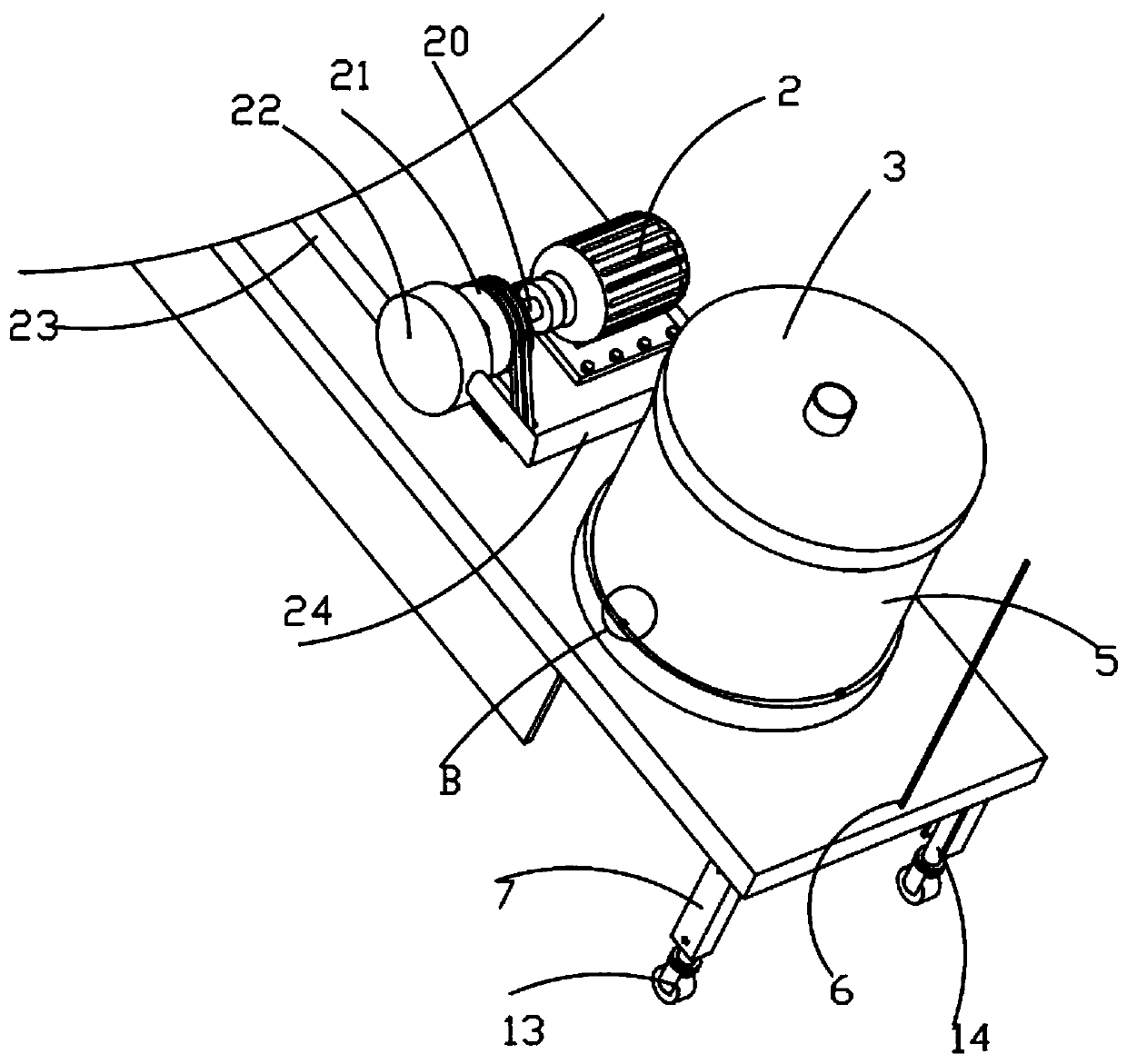
[0048] Such as Figure 1-8 The top of bottom plate 1 shown is fixedly connected with ring 8, drive motor 2, hollow drum 22, electric push rod 19, mounting cylinder 10 and push handle 15, and the top of push handle 15 is fixedly connected with two sets of identical switches 41, switch 41 The drive motor 2 and the electric push rod 19 are respectively electrically connected, the switch 41 is fixedly connected with the cable 16, the cable 16 is electrically connected with the external power supply through the socket, the ring 8 is connected with an air filter structure, and the air filter structure includes a dust removal cylinder 5 , the dust removal cylinder 5 is plugged into the ring 8, the top of the dust removal cylinder 5 is threadedly connected with a cover plate 5, the bottom of the cover plate 5 is fixedly connected with a filter screen 35 for dust filtration, and the top of the cover plate 5 is fixedly conn...
PUM
 Abstract
Description
Claims
Application Information