
Frequency-adaptable structural health and usage monitoring system

a technology of structural health and monitoring system, which is applied in the direction of structural/machine measurement, using mechanical means, instruments, etc., can solve the problems of system maintenance or replacement, adversely affecting the operational life of a component or subsystem, and simple analog sensors do not have their own processing power

Active Publication Date: 2013-08-15
APPAREO SYST
View PDF5 Cites 70 Cited by
  • Summary
  • Abstract
  • Description
  • Claims
  • Application Information

AI Technical Summary

Benefits of technology

The present invention is a system for monitoring the health and usage of dynamic mechanical systems. The system can operate in several different modes, which means it can be used on older systems without needing to change or upgrade any parts. This makes it easier to monitor the health of these machines and avoid downtime.

Problems solved by technology

For example, a change in the characteristic frequency of vibration detected from a monitored gearbox may indicate that a mechanical component such as a bearing or gear within the gearbox has failed or is in the process of failing, and therefore the system is in need of maintenance or needs to be replaced.
Such exceedances can adversely affect the operational life of a component or subsystem and must be taken into account when forecasting the expected remaining life.
These simple analog sensors do not have their own processing power and do not store data for later transmission.
As a result of the weak signal strength of many of these sensors, the sensors that are not located very close to the digitizer often require amplification prior to signal transmission so as to insure signal integrity at the digitizer, which adds further cost and complexity to the system.
SHMSs used to monitor aircraft in flight, particularly those systems used to monitor helicopters, face a unique set of challenges.
Further compounding the problem is that, for data to be useful in comparative analysis, all of the data from a particular event should be taken during a period of time in which the flight dynamics of the aircraft are constant.
More complex and expensive systems, which include inertial sensors or which have access to inertial data on a data bus, may trigger recording events automatically when prescribed points of stationarity are detected.
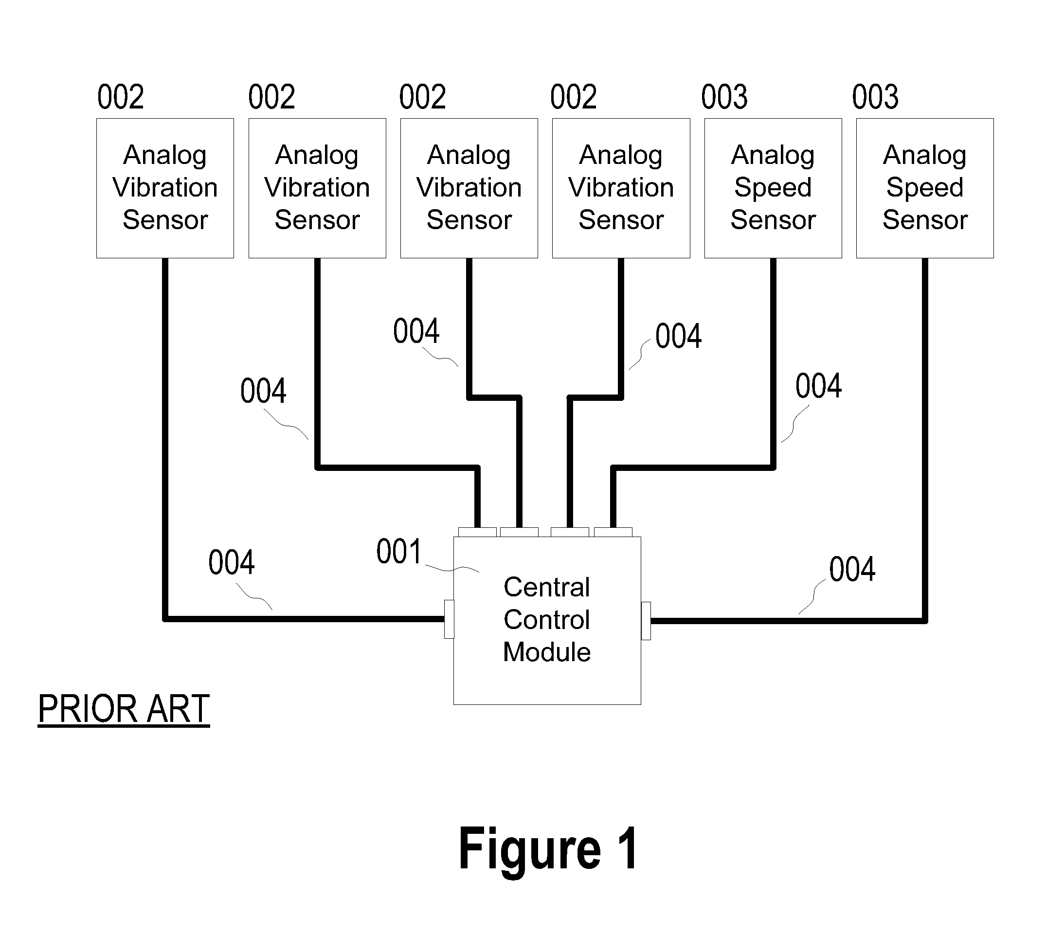
Some of these shortcomings are as follows:Wiring can be expensive, heavy, and fragile.
The coaxial cables used are both fragile and expensive.
If the cables are crimped or compressed they can attenuate the signals from the sensors to such a degree that the information transmitted is lost.
Given that each sensor must have its own unique cable, rather than, for example, sharing a common data bus, the amount of wiring on a modern aircraft can be substantial, adding unnecessarily to the aircraft's weight.Manual initiation of system recording can introduce both safety and accuracy concerns.
Requiring the pilot to take such action increases the risk that the distraction so imposed might, under unique situations, (unanticipated turbulence for example) impair the safe operation of the aircraft.
In addition, if the pilot misinterprets the actual flight characteristics of his aircraft (that is, the aircraft is not actually in straight and level flight for the required duration of the measurement) then the data acquired may actually be useless for purposes of aircraft health determination.Large amounts of analog data acquired necessitate heavy, expensive digitizers and storage equipment.
Because the sensors are “dumb” (no processing power), they simply record raw data and send everything over the cables to the control unit, which must then deal with this large amount of potentially rapidly-changing data.Poor signal quality.
Simple analog sensors often require the use of signal amplifiers to avoid attenuation of the signals as they travel from the point of detection to the central control unit.Lack of adaptability.
Existing HUMS cannot automatically adapt to the changing base frequency caused by a change in the base central speed, such as the engine speed of an aircraft as it moves into and through different flight regimes.
Airborne systems may only be able to effectively monitor an aircraft in known and controlled flight regimes (such as hovering or on the ground).
None of the systems described above use intelligent sensors (that is, vibration or other HUMS sensors which have a significant amount of processing power integral to their bodies), cannot automatically detect flight regimes, and do not automatically adjust the range of “frequencies of interest” based on a key system frequency signal.

Method used


Image

  • Frequency-adaptable structural health and usage monitoring system
  • Frequency-adaptable structural health and usage monitoring system
  • Frequency-adaptable structural health and usage monitoring system

Examples


Embodiment Construction

I. Introduction and Environment

[0053]As required, detailed embodiments of the present invention are disclosed herein; however, it is to be understood that the disclosed embodiments are merely exemplary of the invention, which may be embodied in various forms. Therefore, specific structural and functional details disclosed herein are not to be interpreted as limiting, but merely as a basis for the claims and as a representative basis for teaching one skilled in the art to variously employ the present invention in virtually any appropriately detailed structure.

[0054]Certain terminology will be used in the following description for convenience in reference only and will not be limiting. For example, up, down, front, back, right and left refer to the invention as oriented in the view being referred to. The words “inwardly” and “outwardly” refer to directions toward and away from, respectively, the geometric center of the embodiment being described and designated parts thereof. Said term...


PUM


Abstract

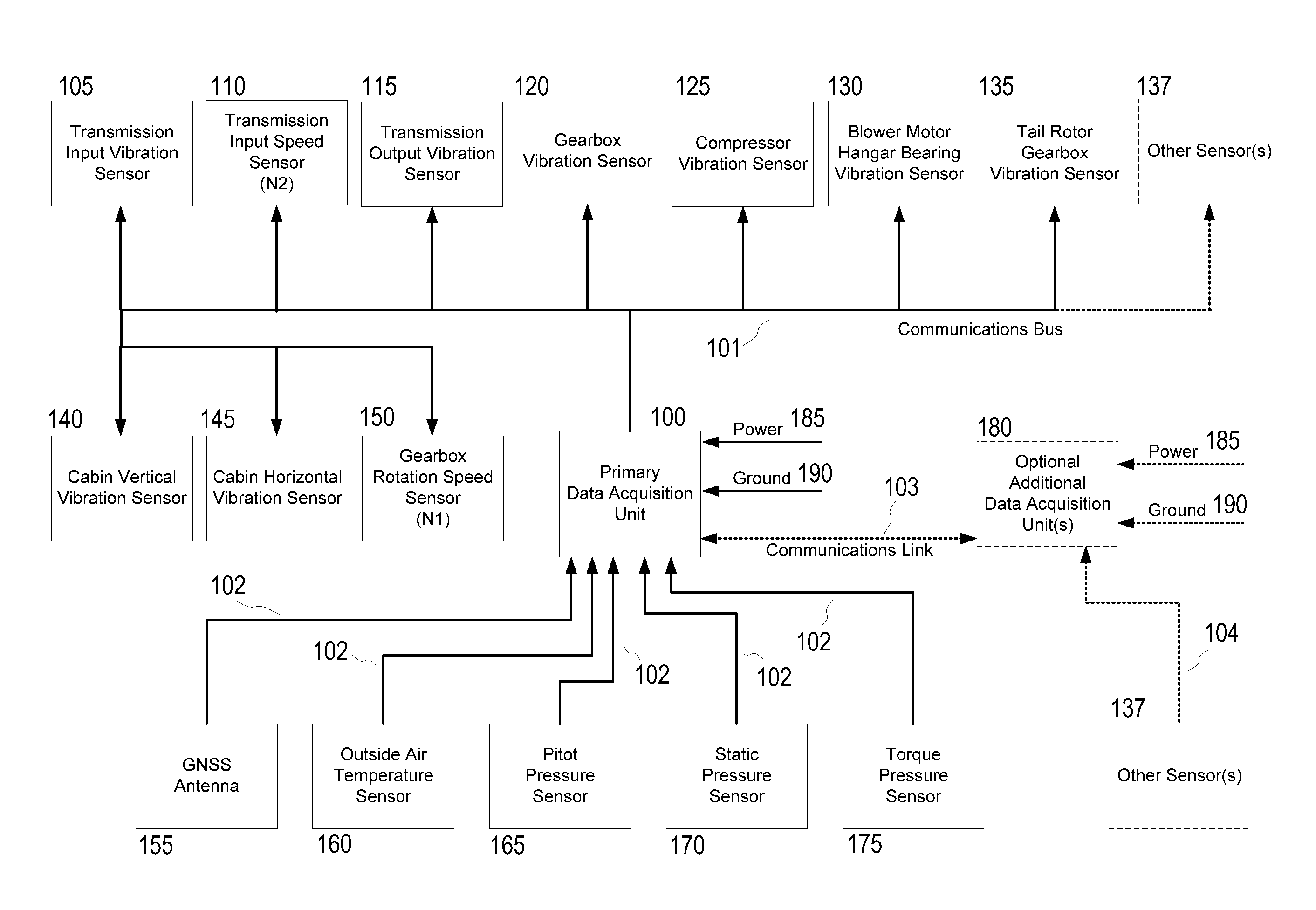
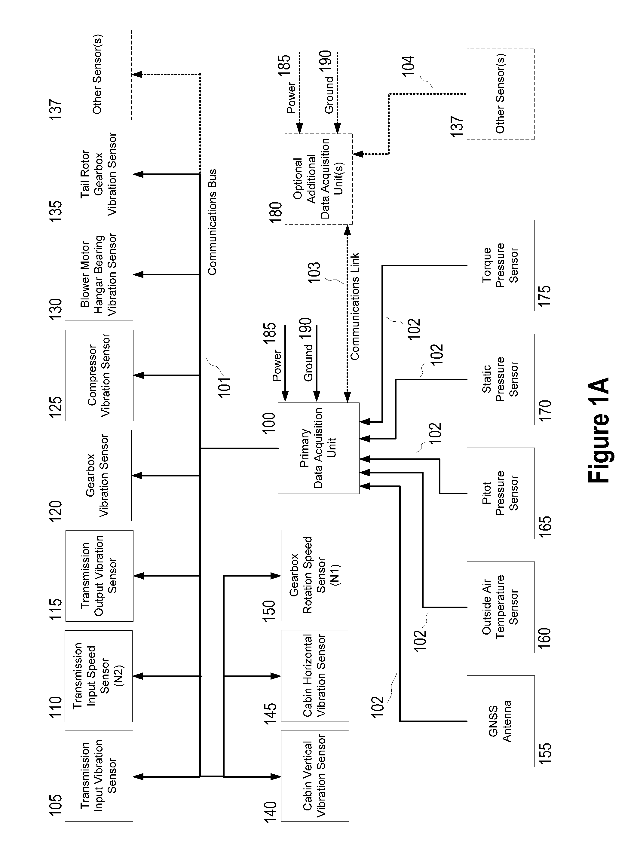
A structural health monitoring system comprising intelligent sensors, wherein the intelligent sensors are individually programmable and can be tuned to listen to specific frequencies based on a scaling factor based on the sensor's location in the system being monitored, a set of pre-known frequencies based on the sensor's location in the system being monitored, and the output of a central frequency-based system sensor.

Description

CROSS-REFERENCE TO RELATED APPLICATION[0001]This application claims priority in U.S. Provisional Patent Application Ser. No. 61 / 597,667, filed Feb. 10, 2012, which is incorporated herein by reference.BACKGROUND OF THE INVENTION[0002]1. Field of the Invention[0003]The present invention relates generally to the field of structural health monitoring (SHM) for damage detection and characterization of engineered structures, and more specifically to such systems employing a network of distributed intelligent sensors.[0004]2. Description of the Related Art[0005]Structural health monitoring systems (SHMSs) have been developed for many applications, from industrial applications such as monitoring manufacturing lines in paper mills to monitoring the structures and equipment of fixed wing aircraft and rotorcraft. A typical SHMS uses deployed sensors to detect the operational characteristics of various components of a system; such characteristics include the speed, vibration, and temperature of...

Claims


Application Information

Patent Timeline
IPC IPC(8): G01M7/00
CPCG07C5/085G01M7/00G01M17/08
Inventor BATCHELLER, BARRY D.WIIG, JOHAN A.
Owner APPAREO SYST
Learn More