
Electronic device

a technology of electronic devices and transducers, applied in the direction of electrical transducers, transducer types, piezoelectric/electrostrictive transducers, etc., can solve the problem of difficult to achieve a small size, and achieve the effect of reducing siz

Inactive Publication Date: 2013-08-22
NEC CORP
View PDF4 Cites 3 Cited by
  • Summary
  • Abstract
  • Description
  • Claims
  • Application Information

AI Technical Summary

Benefits of technology

The invention is for a small electronic device that can control how a sound comes out of a special speaker. This helps reduce the size of the device and make it easier to control the sound direction.

Problems solved by technology

Thus, in an electronic device mounted with the oscillators, it is difficult to achieve a small size.

Method used


Image

  • Electronic device
  • Electronic device
  • Electronic device

Examples


Embodiment Construction

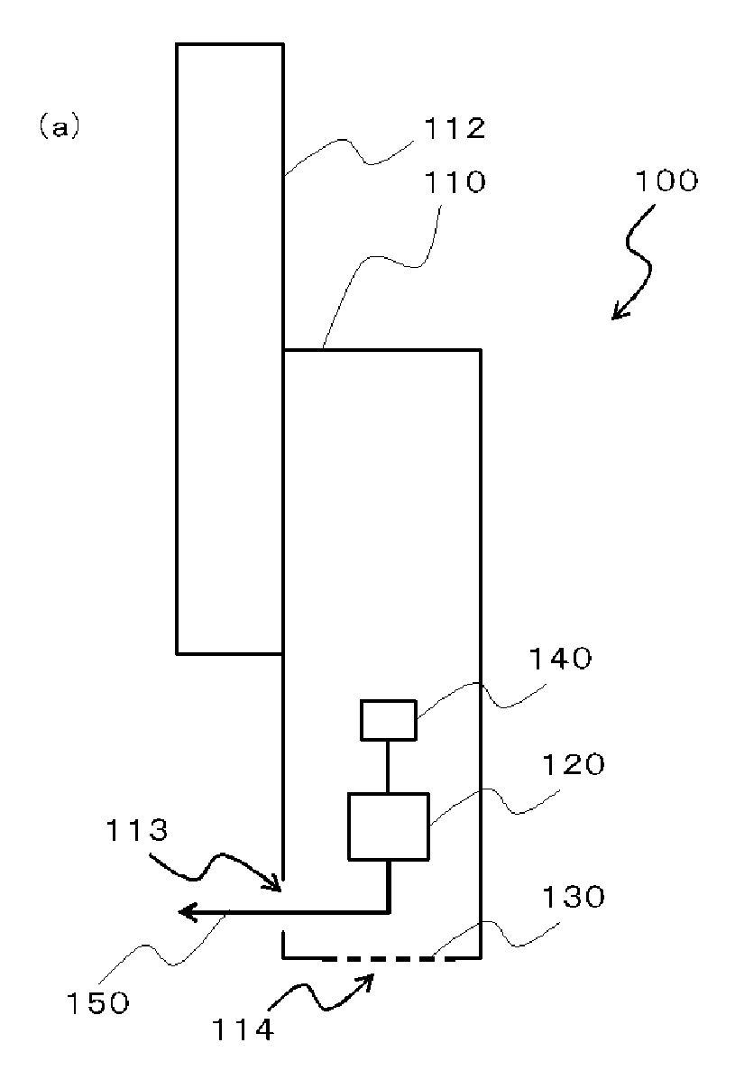
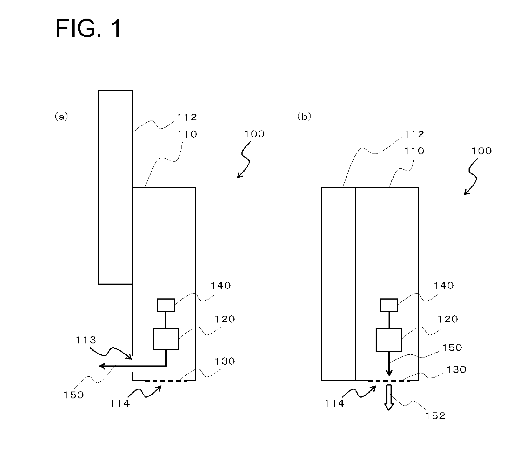
[0020]An embodiment of the invention will be described with reference to the accompanying drawings. FIG. 1 is a longitudinal sectional side view schematically illustrating an internal structure of an electronic device 100 according to the present embodiment.

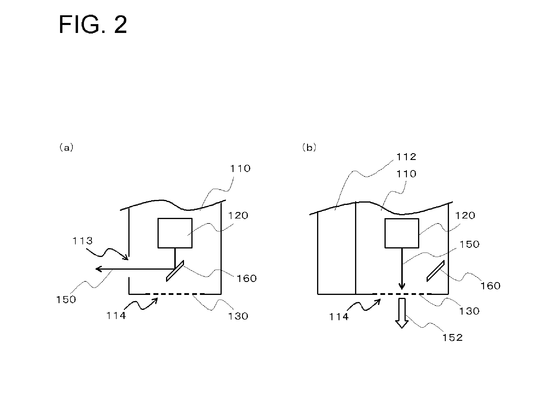
[0021]The electronic device 100 of the present embodiment includes a housing 110 provided with at least one sound hole 113 and at least one sound hole 114, an oscillator 120 that is disposed in the housing 110 and outputs a modulated wave for a parametric loudspeaker, a sound demodulating unit 130 that is not mounted in the sound hole 113 but mounted in the sound hole 114 and demodulates the modulated wave, and a sound hole opening and closing unit 112 that is mounted in the housing 110 and opens and closes the sound hole 113 as shown in FIG. 1.

[0022]The electronic device 100 is a mobile communication terminal such as a mobile phone or the like, for example.

[0023]As shown in FIG. 1, the sound hole opening and closing unit 112 is ...


PUM


Abstract

Disclosed is an electronic device including: a housing (110) in which at least one sound hole (113) and at least one sound hole (114) are formed; an oscillator (120) that is provided inside the housing (110) and outputs a modulated wave for a parametric loudspeaker; a sound demodulation unit (130) that is not provided in the sound hole (113) but provided in the sound hole (114) and demodulates the modulated wave; and a sound hole opening and closing unit (112) that is mounted to the housing (110) and opens and closes the sound hole (113).

Description

TECHNICAL FIELD[0001]The present invention relates to an electronic device provided with an oscillator.BACKGROUND ART[0002]Recently, a parametric loudspeaker that demodulates an ultrasonic wave passed through amplitude modulation (AM) or frequency modulation (FM) by using a density phenomenon of air to reproduce audible sound has been developed.[0003]In the parametric loudspeaker, the ultrasonic wave is used. Thus, it is possible to realize an audio device with a high directionality. With the audio device with the high directionality, for example, it is possible to propagate sound to only a specific user, thereby making it possible to provide saleability such as privacy protection. Further, for example, it is possible to provide a function of propagating sound to only a specific position.[0004]In order to control an output direction of a sound output from the parametric loudspeaker, a phased array method is used, for example. In the phased array method, ultrasonic waves oscillated a...

Claims


Application Information

Patent Timeline
Patent Type & Authority Applications(United States)
IPC IPC(8): H04R1/02
CPCH04M1/035H04R1/345H04R1/021H04R2217/03H04R2499/11H04R17/00G10K15/04
Inventor KISHINAMI, YUICHIROONISHI, YASUHARUKOMODA, MOTOYOSHIKAWASHIMA, NOBUHIROMURATA, YUKIOKURODA, JUNSATOU, SHIGEO
Owner NEC CORP
Learn More