Method for manufacturing integral imaging device

a manufacturing method and imaging device technology, applied in the field of stereo displays, can solve problems such as difficulty and/or inefficiency

Inactive Publication Date: 2013-08-22
HON HAI PRECISION IND CO LTD
View PDF5 Cites 22 Cited by
  • Summary
  • Abstract
  • Description
  • Claims
  • Application Information

AI Technical Summary

Problems solved by technology

To ensure display quality, it is required that the cylindrical lenses precisely align with the pixels, which is difficult and / or inefficient.

Method used


Image

  • Method for manufacturing integral imaging device
  • Method for manufacturing integral imaging device
  • Method for manufacturing integral imaging device

Examples


Embodiment Construction

[0009]Embodiments of the disclosure will be described in detail, with reference to the accompanying drawings.

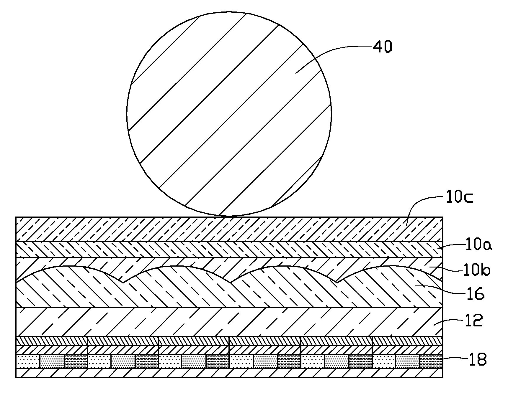
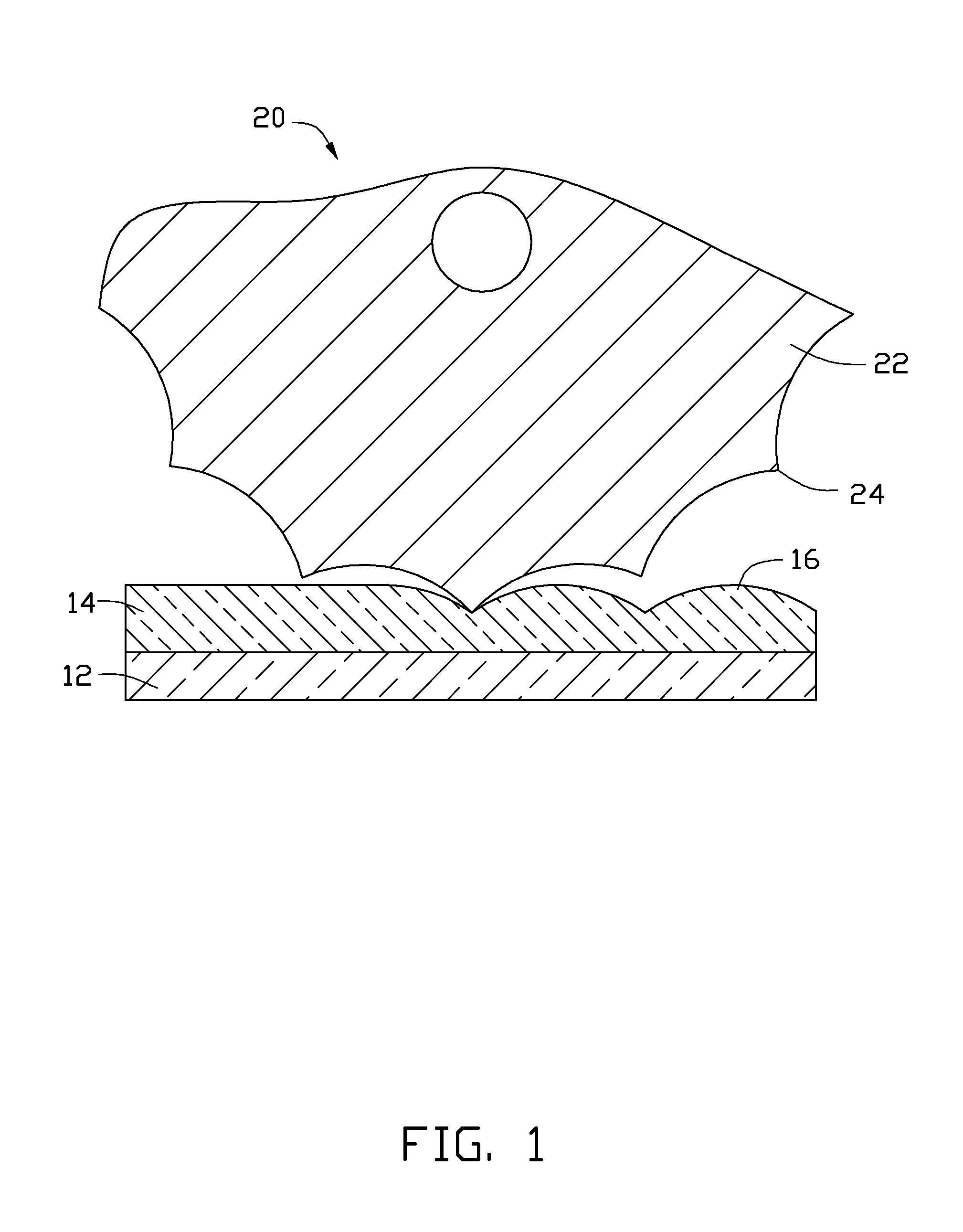
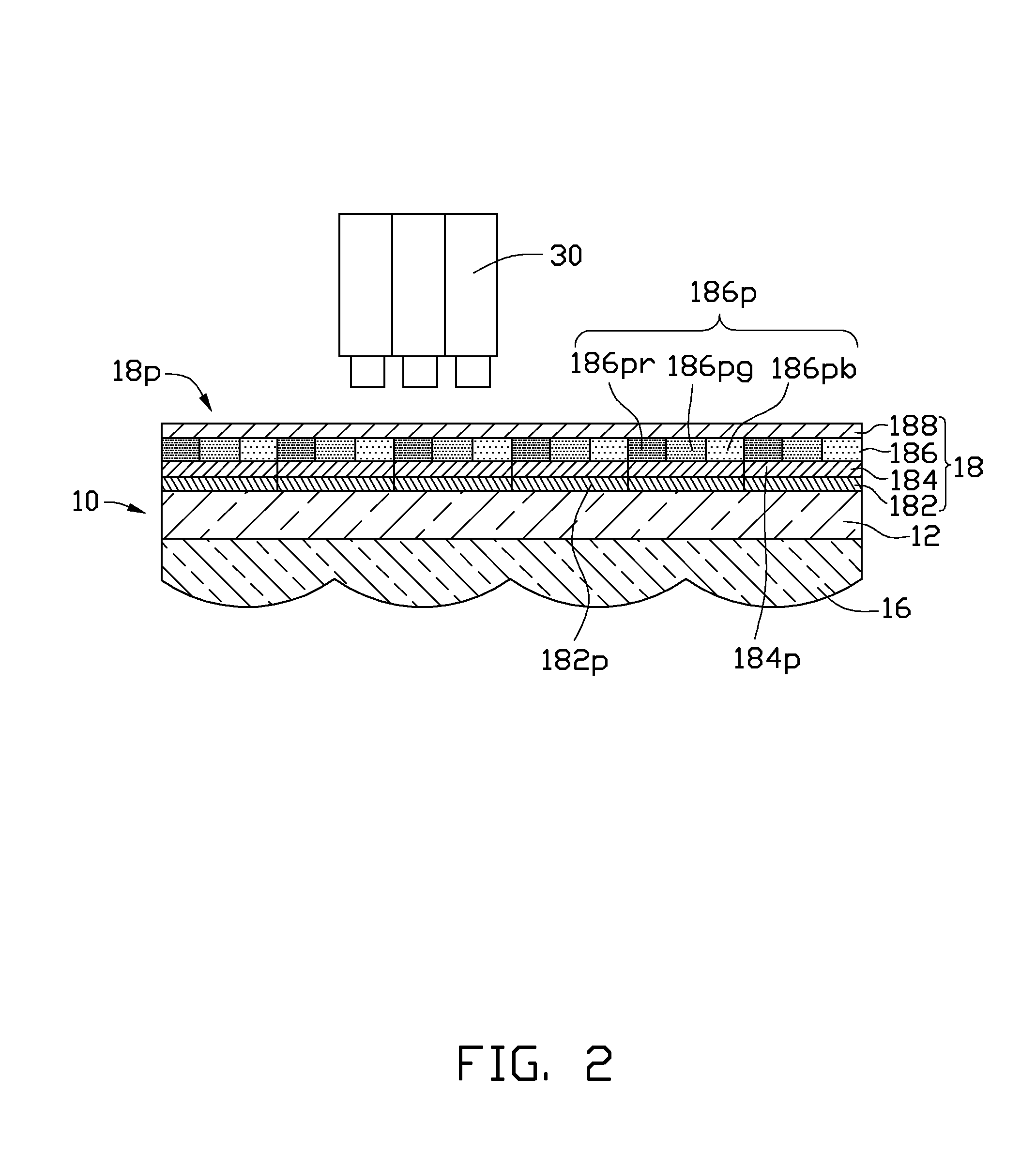
[0010]Referring to FIGS. 1 and 2, a method for manufacturing an integral imaging device 10 includes the following steps S01-S05.

[0011]In step S01, a layer of curable adhesive 14 is applied on a flexible substrate 12 and is half cured such that the curable adhesive 14 is solidified but can be deformed by external forces. As such, the curable adhesive 14 can be shaped as desired.

[0012]The flexible substrate 12 can be a hot melt adhesive film, such as a polyethylene terephthalate (PET) or a polyether sulfone (PES) film. The curable adhesive 14 can be ultraviolet (UV) curable adhesive.

[0013]In step S02, the curable adhesive 14 is printed by a roll-to-roll (R2R) processing device 20 to form a lenticular lens 16 having a predetermined shape and size and is fully cured such that the curable adhesive 14 can withstand external force to hold the predetermined shape and size.

[0014]The R...


PUM


Abstract

In a method for manufacturing an integral imaging device, a layer of curable adhesive is first applied on a flexible substrate and half cured such that the curable adhesive is solidified but is capable of deforming under external forces. Then the curable adhesive is printed into a lenticular lens having a predetermined shape and size using a roll-to-roll processing device and fully cured such that the curable adhesive is capable of withstanding external forces to hold the predetermined shape and size. Last, a light emitting diode display is applied on the flexible substrate opposite to the lenticular lens such that an image plane of the light emitting diode display coincides with a focal plane of the lenticular lens.

Description

BACKGROUND[0001]1. Technical Field[0002]The present disclosure relates to stereo displays and, particularly, to a method for manufacturing an integral imaging device.[0003]2. Description of Related Art[0004]Integral imaging devices display a 3D image using lenticular lenses, each of which include an array of cylindrical lenses, precisely aligned in front of an array of image pixels, where each cylindrical lens looks different depending on viewing angle, thus creating a stereo effect that exhibits parallax when viewers move. To ensure display quality, it is required that the cylindrical lenses precisely align with the pixels, which is difficult and / or inefficient.[0005]Therefore, it is desirable to provide a method for manufacturing an integral imaging device which can overcome the above-mentioned shortcomings.BRIEF DESCRIPTION OF THE DRAWINGS[0006]FIG. 1 is a schematic view showing how to implement a step of a method for manufacturing an integral imaging device according to an embod...

Claims


Application Information

Patent Timeline
Patent Type & Authority Applications(United States)
IPC IPC(8): H01L33/58
CPCH01L33/58H01L25/0753G02B27/2214H04N2213/001G02B3/0031H04N13/0404H01L2924/0002H04N13/305H01L2924/00G02B30/27
Inventor HSU, CHIA-LING
Owner HON HAI PRECISION IND CO LTD
Why Eureka
Try Eureka