Illumination optical system, light irradiation apparatus for spectrometry, and spectrometer

a light irradiation apparatus and optical system technology, applied in the direction of near-field systems using receivers, near-field systems for read/write/interrogation/identification, instruments, etc., can solve the problems of difficult to stably transmit and receive information between non-contact ic cards and r/w devices, and achieve the effect of stable communication characteristi

Active Publication Date: 2013-08-22
SONY CORP
View PDF9 Cites 10 Cited by
  • Summary
  • Abstract
  • Description
  • Claims
  • Application Information

AI Technical Summary

Benefits of technology

[0018]As described above, according to the portable communication device and resonant frequency adjustment method of the present invention, the parameter including the information on the transmission state of the adjustment signal is detected when the adjustment signal adjusting the received resonant frequency is transmitted to the receiver of the portable communication device. The received resonant frequency is adjusted based on the detected parameter.
[0019]According to the reader / writer device of the present invention, when the adjustment signal is transmitted to the transmitter, the parameter including the information on the transmission state of the adjustment signal is detected, and the transmission resonant frequency is adjusted based on the detection result.
[0020]That is, according to the present invention, even if the received resonant frequency and / or the transmission resonant frequency are deviated by various causes, the deviations of the resonant frequencies can easily adjusted in the own device, and the stable communication characteristic can be obtained.

Problems solved by technology

In this case, it is difficult to stably transmit and receive information between the non-contact IC card and the R / W device.

Method used


Image

  • Illumination optical system, light irradiation apparatus for spectrometry, and spectrometer
  • Illumination optical system, light irradiation apparatus for spectrometry, and spectrometer
  • Illumination optical system, light irradiation apparatus for spectrometry, and spectrometer

Examples


first embodiment

1. First Embodiment

[Communication of Mobile Communication Terminal]

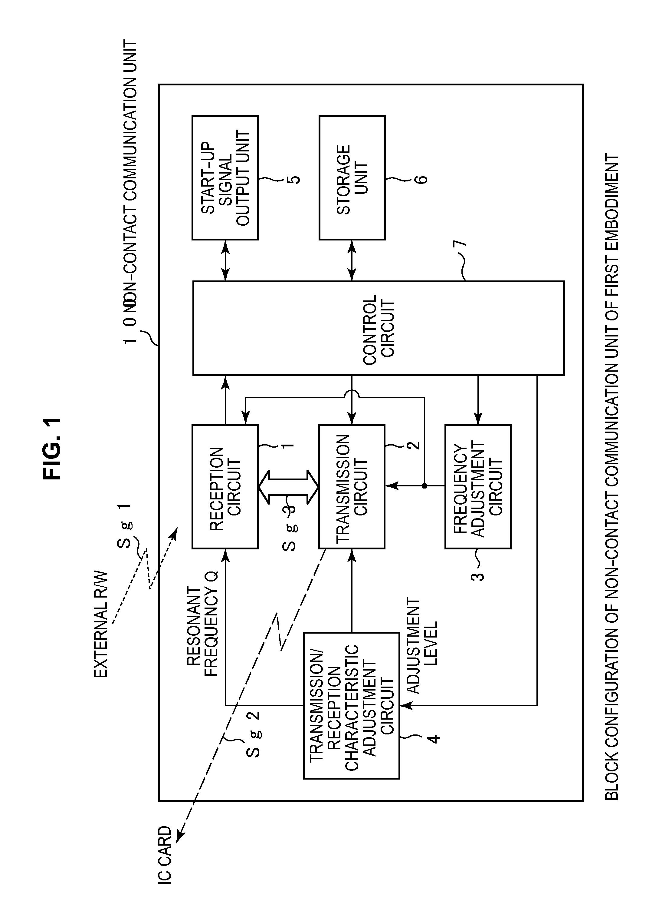
[0042]FIG. 1 illustrates a schematic configuration of a mobile communication terminal according to a first embodiment of the present invention. For the sake of convenience, only a configuration (hereinafter referred to as a non-contact communication unit) necessary for both an IC card function and an R / W function is illustrated in FIG. 1. However, a configuration except the non-contact communication unit may be identical to that of the conventional mobile communication terminal. In the first embodiment, an adjustment of a resonant frequency (the received resonant frequency) of a reception circuit system (the IC card function) in a non-contact communication unit is described by way of example.

[0043]A non-contact communication unit 100 includes a reception circuit 1, a transmission circuit 2 (the transmitter), a frequency adjustment circuit 3, a transmission / reception characteristic adjustment circuit 4, a start-up sig...

second embodiment

2. Second Embodiment

[0206]A received resonant frequency adjustment technique (hereinafter referred to as an offset adjustment) in the case that the carrier frequency of the adjustment signal Sg3 and the resonant frequency of the reception circuit 1 differ from each other will be described in a second embodiment.

[0207]Although the second embodiment differs from the first embodiment in the received resonant frequency adjustment technique, the second embodiment is identical to the first embodiment in the configurations of the mobile communication terminal and non-contact communication unit (FIGS. 1 and 2). Therefore, in the second embodiment, the description of each unit of the mobile communication terminal is omitted and only the received resonant frequency offset adjustment technique is described. However, the control circuit 7 controls the received resonant frequency offset adjustment of the second embodiment.

[0208]In the second embodiment, because reference data 1 or 2 is used in t...

third embodiment

3. Third Embodiment

[0236]In the first and second embodiments, by way of example, the transmission antenna 20 and the reception antenna 30 are separately provided in the non-contact communication unit 100. However, the present invention is not limited to the first and second embodiments. The present invention can also be applied to the case that one antenna is commonly used as the reception antenna and the transmission antenna in the non-contact communication unit. A configuration example in which one antenna is commonly used as the reception antenna and the transmission antenna in the non-contact communication unit will be described in a third embodiment.

[0237][Configuration of Transmission / Reception Circuit]

[0238]FIG. 19 illustrates a schematic configuration of a transmission / reception sharing circuit in a non-contact communication unit of the third embodiment. A transmission / reception sharing circuit 80 of the third embodiment has a configuration in which the reception circuit 1 a...


PUM


Abstract

Provided is a portable communication device including a receiver, a transmitter, an adjustment signal generator, an adjustment signal detector, and a control circuit unit. The transmitter transmits an adjustment signal to the receiver in order to adjust a received resonant frequency. The adjustment signal detector detects a parameter including information on a transmission state of the adjustment signal at a time of transmitting the adjustment signal. Then, the control circuit unit corrects a deviation of the received resonant frequency based on a detection result of the adjustment signal detector.

Description

TECHNICAL FIELD[0001]The present invention relates to a portable communication device including a function of conducting communication with an external device in a non-contact manner by electromagnetic induction, a reader / writer device, and a resonant frequency adjustment method in the devices.BACKGROUND ART[0002]Nowadays a non-contact communication system in which non-contact IC (Integrated Circuit) cards, such as a traffic ticket and electronic money, are used becomes significantly widespread. In such a non-contact communication system, a transmission signal (electromagnetic wave) emitted from a transmission antenna (a resonant circuit) of a reader / writer (hereinafter abbreviated to as R / W) device dedicated to the system is received by the electromagnetic induction using a reception antenna provided in the non-contact IC card.[0003]In the non-contact communication system, a resonant frequency of the reception antenna of the non-contact IC card or the transmission antenna of the R / ...

Claims


Application Information

Patent Timeline
Patent Type & Authority Applications(United States)
IPC IPC(8): H04B5/00
CPCG06K19/0726H04B5/0056G06K17/00H04B1/59H04B5/02
Inventor KANNO, MASAYOSHIORIHARA, KATSUHISASAITO, NORIOSUGITA, SATORU
Owner SONY CORP
Why Eureka
Try Eureka