Photoelectric conversion element, dye-sensitized solar cell, dye composition, and oxide semiconductor electrode

a conversion element and solar cell technology, applied in the direction of methine/polymethine dyes, electrolytic capacitors, ruthenium organic compounds, etc., can solve the problems of natural limitations in throughput improvement, cost, and improvement, and achieve the effect of reducing large deviation width among elements, and large deviation of photoelectric conversion efficiency

Inactive Publication Date: 2018-07-19
FUJIFILM CORP
View PDF2 Cites 1 Cited by
  • Summary
  • Abstract
  • Description
  • Claims
  • Application Information

AI Technical Summary

Benefits of technology

[0010]However, in the photoelectric conversion elements and the dye-sensitized solar cells, with regard to metal complex dyes in the related art, a deviation of photoelectric conversion efficiency among the elements at an initial time (after the production) is easily generated, and particularly in a low-illumination environment, the deviation width among the elements is large in the photoelectric conversion efficiency at an initial time increases.
[0011]It is an object of the present invention to provide a photoelectric conversion element and a dye-sensitized solar cell, each of has a reduced deviation of photoelectric conversion efficiency among photoelectric conversion elements, as well as a dye composition and an oxide semiconductor electrode, each of which is used in the photoelectric conversion element and the dye-sensitized solar cell.
[0012]The present inventors have conducted various studies on a metal complex dye used for a photoelectric conversion element and a dye-sensitized solar cell, and thus, have found that it is possible to reduce the deviation of photoelectric conversion efficiency even in a low-illumination environment with a photoelectric conversion element, by using a metal complex dye having a bipyridine ligand having a p-diphenylaminostyryl group or the like at the 4-position of each pyridine ring, a bipyridine ligand having a carboxyl group in each pyridine ring, and two isothiocyanate groups, together with a metal complex dye in which at least one isothiocyanate group is changed to a specific monodentate ligand, as the metal complex dye of the photoelectric conversion element. Based on these findings, the present invention has been completed by further repeating the studies.

Problems solved by technology

In particular, solar cells utilizing inexhaustible solar energy do not necessitate fuels, and full-fledged practicalization of solar cells as an inexhaustible clean energy is being highly expected.
However, silicon is an inorganic material, and thus, naturally has limitations in terms of improvement of throughput, cost, and the like.

Method used


Image

  • Photoelectric conversion element, dye-sensitized solar cell, dye composition, and oxide semiconductor electrode
  • Photoelectric conversion element, dye-sensitized solar cell, dye composition, and oxide semiconductor electrode
  • Photoelectric conversion element, dye-sensitized solar cell, dye composition, and oxide semiconductor electrode

Examples


example 1 (

Synthesis of Metal Complex Dye)

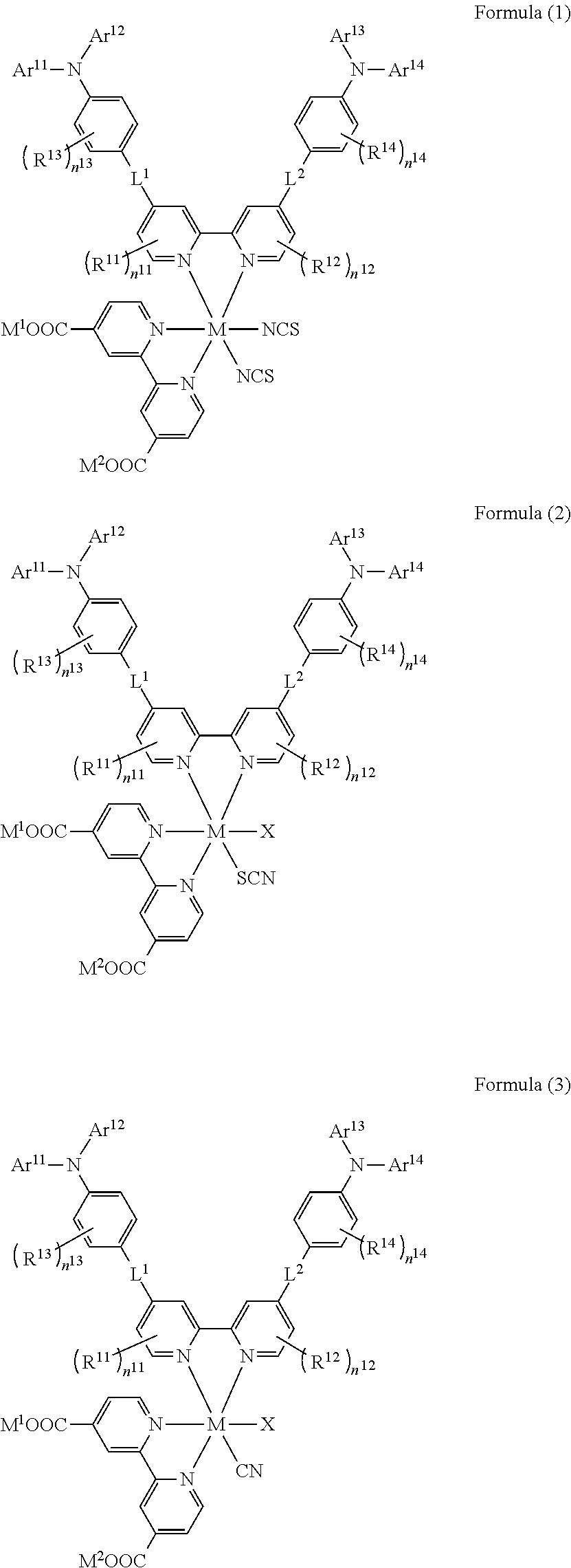
[0264]The structures of the metal complex dyes D-E1 to D-E11 synthesized in the present Examples are shown below.

[0265]In Examples, metal complex dyes D-E1-1 to D-E1-3 may be collectively referred to a metal complex dye D-E1 in some cases. This shall also apply to a case of metal complex dyes D-E2 to D-E11.

[0266]Each of the metal complex dyes D-E4-1 to 3 is represented by a metal complex dye of each of Formulae (1) to (3) in which M1 is a potassium ion and M2 is a proton, but may be the metal complex dye in which M1 is a proton and M2 is a potassium ion or may be a mixture of the metal complex dye in which M1 is a potassium ion and M2 is a hydrogen atom, and the metal complex dye in which M1 is a hydrogen atom and M2 is a potassium ion. This shall also apply to a case of metal complex dye D-E5 to D-E11.

[0267]Incidentally, in the metal complex dyes D-E to D-E11, X represents —NCS or —SCN, and in the following metal complex dyes, Et represents ethyl, nBu...

example 2 (

Production of Dye-Sensitized Solar Cell)

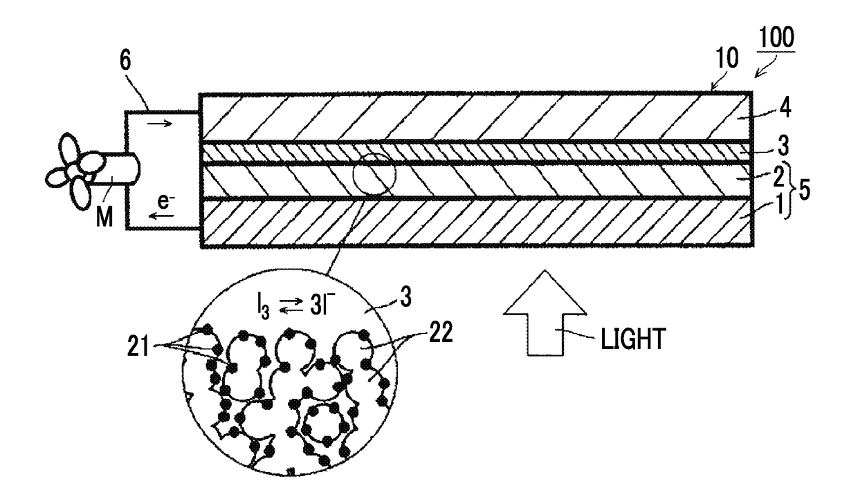
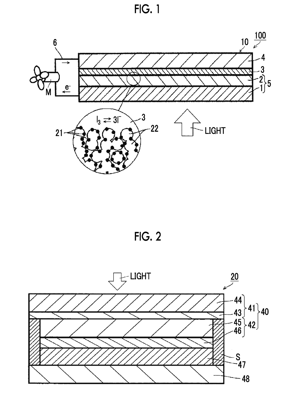
[0311]A dye-sensitized solar cell 20 (in a scale of 5 mm×5 mm) shown in FIG. 2 was produced by a procedure shown below, using each of the metal complex dyes synthesized in Example 1 or each of the following comparative compounds (C1) to (C3), and the following performance was evaluated. The results are shown in Tables 2-1 and 2-2 (which are sometimes referred to Table 2).

[0312](Manufacture of Light-Receiving Electrode Precursor)

[0313]An electrically conductive support 41 having a fluorine-doped SnO2 electrically-conductive film (transparent electrically-conductive film 43, film thickness of 500 nm) on a glass substrate (substrate 44, thickness of 4 mm) was manufactured. Further, the glass substrate having the SnO2 electrically-conductive film formed thereon was immersed in a 40 mM aqueous titanium trichloride solution for 30 minutes, washed with ultrapure water and ethanol, and then calcined at 450° C. to form a thin film layer of a titania co...


PUM

PropertyMeasurementUnit
molar ratioaaaaaaaaaa

Abstract

Provided are a photoelectric conversion element including an electrically conductive support, a photoconductor layer, a charge transfer layer, and a counter electrode, in which the photoconductor layer has semiconductor fine particles carrying a metal complex dye represented by Formula (1), and at least one of metal complex dyes represented by Formulae (2) and (3), a dye-sensitized solar cell, a dye composition, and an oxide semiconductor electrode.
In the formulae, M represents a metal ion. Ar11 to Ar14 each represent an aryl group or the like. L1 and L2 each represent an ethenylene group or the like. R11 to R14 each represent an alkyl group or the like. n11 and n12 each represent an integer of 0 to 3, and n13 and n14 each represent an integer of 0 to 4. X represents —NCS or —SCN. M1 and M2 each represent a proton, a metal cation, or a non-metal cation.

Description

CROSS-REFERENCE TO RELATED APPLICATIONS[0001]This application is a Continuation of PCT International Application No. PCT / JP2016 / 075816 filed on Sep. 2, 2016, which claims priorities under 35 U.S.C. § 119 (a) to Japanese Patent Application No. JP2015-184069 filed on Sep. 17, 2015, Japanese Patent Application No. JP2015-247573 filed on Dec. 18, 2015, and Japanese Patent Application No. JP2016-087843 filed on Apr. 26, 2016. Each of the above applications is hereby expressly incorporated by reference, in its entirety, into the present application.BACKGROUND OF THE INVENTION1. Field of the Invention[0002]The present invention relates to a photoelectric conversion element, a dye-sensitized solar cell, a dye composition, and an oxide semiconductor electrode.2. Description of the Background Art[0003]Photoelectric conversion elements are used in various photosensors, copying machines, photoelectrochemical cells such as solar cells, and the like. These photoelectric conversion elements have a...

Claims


Application Information

Patent Timeline
Patent Type & Authority Applications(United States)
IPC IPC(8): H01G9/20H01L51/00C09B57/10
CPCH01G9/2031H01G9/2022H01G9/204H01L51/0086C09B57/10Y02E10/542C09B23/145Y02E10/549H01G9/2063H10K85/344C07F15/0046H01G9/2027
Inventor WATANABE, KOUSUKETANI, YUKIOSHIROKANE, KENJIYOSHIOKA, TOMOAKISASAKI, KOUITSU
Owner FUJIFILM CORP
Why Eureka
Try Eureka