
Molded case circuit breaker

a circuit breaker and molded case technology, applied in the direction of electrical equipment, switches with electrothermal release, emergency protective devices, etc., can solve the problems of difficult to accurately match the dial b>5, trip operation cannot be performed, etc., and achieve the effect of reducing manufacturing costs and easily deviating

Active Publication Date: 2017-09-05
LSIS CO LTD
View PDF7 Cites 1 Cited by
  • Summary
  • Abstract
  • Description
  • Claims
  • Application Information

AI Technical Summary

Benefits of technology

[0017]Therefore, an aspect of the detailed description is to provide a molded case circuit breaker in which by improving a structure of a dial included in the molded case circuit, a rated current is adjusted without an error, a whole structure is simplified, the manufacturing cost is reduced, and the dial fixed to the molded case circuit breaker is prevented from easily deviating from the molded case circuit.
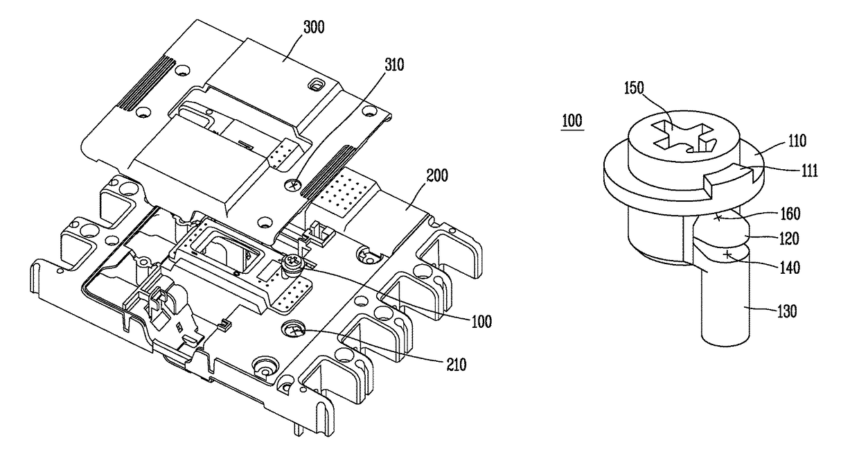
[0024]As described above, in the molded case circuit breaker according to an exemplary embodiment of the present invention, the first stopper may be included in the dial, the first stopper may be fitted into the fitting groove provided in the dial rotation adjusting unit according to a rotation of the dial, and thus, the dial may be stably fixed to a position corresponding to a desired rated current value of the molded case circuit breaker. Therefore, the rated current value may be accurately displayed to the outside, and moreover, the dial may move to a certain degree due to an external impact to change the rated current value, thereby preventing a malfunction of the molded case circuit breaker from being performed.
[0025]Moreover, the dial rotation adjusting unit may be provided in the upper cover and may adjust a rotation of the dial without a separate apparatus for fixing the dial, and thus, a whole structure is simplified, the manufacturing cost is reduced, and a time taken in manufacturing the molded case circuit breaker is shortened.
[0026]Moreover, the auxiliary cover may be coupled to the upper end of the upper cover, and moreover, the moving groove may be provided in order for the second stopper to be fitted into the auxiliary cover and moved. Also, the moving groove may be provided at a portion except the moving bar fitting hole and a periphery of the moving bar fitting hole. Therefore, when the auxiliary cover is coupled to the upper cover, the dial is prevented from being further moved toward the moving bar fitting hole in a state where the dial rotates to a certain degree from the moving bar fitting hole, and thus, the auxiliary cover prevents the dial from deviating from a normal position to the outside.

Problems solved by technology

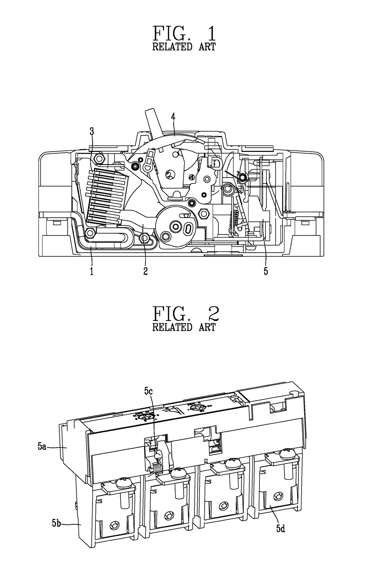
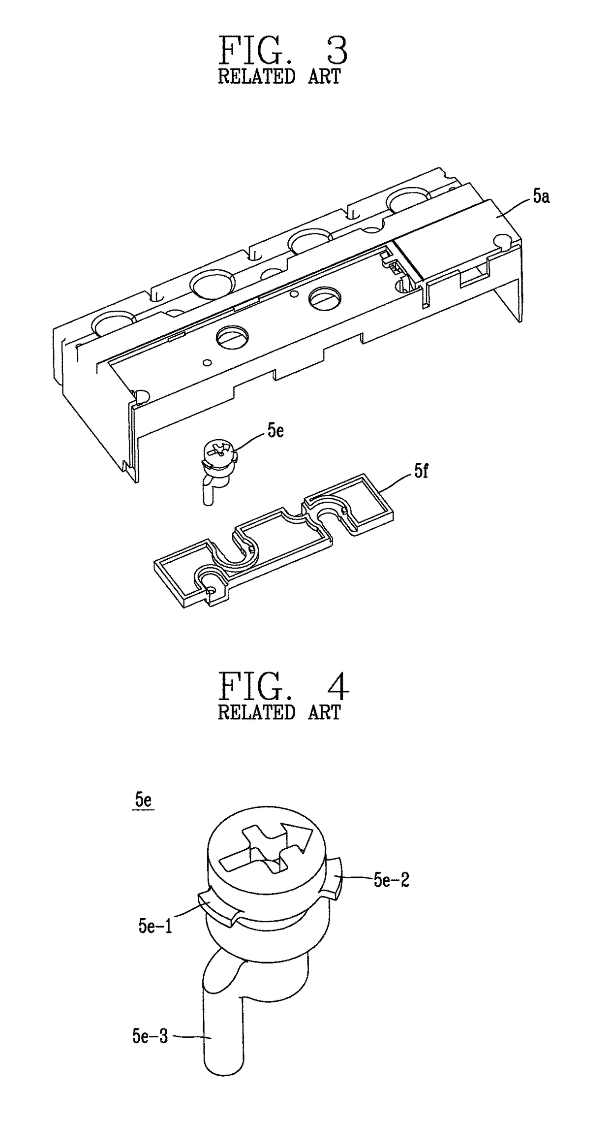
However, as described above, in the dial 5e of the related art for adjusting the rated current of the molded case circuit breaker, it is difficult to accurately match the dial 5e with a desired value of the rated current when rotating the dial 5e.
For this reason, despite a fault current being applied to the molded case circuit breaker, a trip operation cannot be performed.

Method used


Image

  • Molded case circuit breaker
  • Molded case circuit breaker
  • Molded case circuit breaker

Examples


Embodiment Construction

[0041]Description will now be given in detail of the exemplary embodiments, with reference to the accompanying drawings. For the sake of brief description with reference to the drawings, the same or equivalent components will be provided with the same reference numbers, and description thereof will not be repeated.

[0042]Hereinafter, a molded case circuit breaker according to an exemplary embodiment of the present invention will be described in detail with reference to the accompanying drawings.

[0043]As illustrated in FIGS. 7 and 8, the molded case circuit breaker according to an exemplary embodiment of the present invention may include a case (not shown) that accommodates a plurality of trip elements and an upper cover 200 that is detachably attached to the case and into which a dial 100 for adjusting a rated current is fitted.

[0044]A plurality of trip elements such as a heater (not shown), a bimetal (not shown), a crossbar (not shown), and / or the like may be provided in the case. W...


PUM


Abstract

Disclosed is a molded case circuit breaker including a case configured to accommodate an element for trip, an upper cover detachable attached to the case, a dial configured to include a fixing plate, which is provided to protrude along an outer circumference surface thereof, and a first stopper disposed under the fixing plate, a crossbar moved by the dial, a first dial fitting hole provided in the upper cover for the dial to be fitted into the first dial fitting hole, and a dial rotation adjusting unit provided in the first dial fitting hole and fitted between the fixing plate and the first stopper to guide a rotation of the dial, the dial rotation adjusting unit including a plurality of fitting grooves arranged at certain intervals. The first stopper is fitted into and fixed to the plurality of fitting grooves according to the rotation of the dial.

Description

CROSS-REFERENCE TO RELATED APPLICATION[0001]Pursuant to 35 U.S.C. §119(a), this application claims the benefit of earlier filing date and right of priority to Korean Patent Application No. 10-2015-0033872, filed on Mar. 11, 2015, the contents of which are hereby incorporated by reference herein in its entirety.BACKGROUND OF THE DISCLOSURE[0002]1. Field of the Disclosure[0003]The present disclosure relates to a molded case circuit breaker, and particularly, to a molded case circuit breaker in which by improving a structure of a dial included in the molded case circuit, a rated current is adjusted without an error, a whole structure is simplified, the manufacturing cost is reduced, and the dial fixed to the molded case circuit breaker is prevented from easily deviating from the molded case circuit.[0004]2. Background of the Disclosure[0005]Generally, a molded case circuit breaker (MCCB) is installed on a switchboard among power distribution equipment provided in factories, buildings, ...

Claims


Application Information

Patent Timeline
Patent Type & Authority Patents(United States)
IPC IPC(8): H01H1/64H01H21/00H01H19/08H01H19/04H01H9/06H01H9/02H01H1/66H01H71/02H01H71/74H01H13/00
CPCH01H71/025H01H71/74H01H71/7427H01H71/7463H01H2071/7481H01H71/0264H01H71/2463H01H73/22
Inventor OH, KYUNGHWAN
Owner LSIS CO LTD
Learn More