Control apparatus for hybrid vehicle

a control device and hybrid technology, applied in the direction of automatic control systems, process and machine control, instruments, etc., can solve the problems of deteriorating affecting the operation of hybrid vehicles in an uncontrolled manner, and comparatively high drive power, so as to reduce the deterioration of fuel economy of hybrid vehicles

Inactive Publication Date: 2013-08-22
TOYOTA JIDOSHA KK
View PDF0 Cites 6 Cited by
  • Summary
  • Abstract
  • Description
  • Claims
  • Application Information

AI Technical Summary

Benefits of technology

[0009]The control apparatus according to the present invention described above is configured to implement the concurrent controls of the movement of the operating point of the above-described engine and the shifting action of the above-described step-variable transmitting portion, such that the electric energy generation / consumption balance value in the overall transmission mechanism consisting of the above-described electrically operated continuously-variable transmitting portion and step-variable transmitting portion is controlled by controlling the change of the rotary motion of each of at least one of the above-described first, second and third rotary elements, so that a shifting shock of the step-variable transmitting portion can be reduced while controlling the electric energy generation / consumption balance to a desired value. Namely, the control apparatus permits an adequate control of the shifting action while reducing deterioration of fuel economy of the hybrid vehicle.
[0010]In one preferred form of the invention, the control apparatus is configured to change rotating speeds of the above-described first, second and third rotary elements at the same rate from values before the above-described shifting action to values to be established after the shifting action. In this case, the electric energy generation / consumption balance can be controlled to a desired value in a practically advantageous manner.
[0011]According to another preferred form of the invention, the control apparatus is configured to control the above-described shifting action such that a pattern of change of a torque difference between an input torque of the above-described step-variable transmitting portion and a torque associated with a reaction force of an element provided in the above-described step-variable transmitting portion matches a pattern of change of a rotating speed of each of the above-described first, second and third rotary elements. In this case, the electric energy generation / consumption balance can be controlled to a desired value in a practically advantageous manner.
[0012]According to a further preferred form of the invention, the control apparatus is configured to control the above-described shifting action such that a sum of an energy amount generated by the above-described engine during the above-described shifting action, an energy amount which is associated with a reaction force generated during the shifting action by an element provided in the above-described step-variable transmitting portion, and an amount of change of a rotary motion energy of each of the above-described first, second and third rotary elements during the above-described shifting action is equal to a predetermined target value of the electric energy generation / consumption balance value. In this case, the electric energy generation / consumption balance can be controlled to a desired value in a practically advantageous manner.
[0013]According to a still further preferred form of the invention, the control apparatus is configured to calculate the above-described sum without taking account of an amount of the electric energy generation / consumption balance value which relates to the above-described first and second electric motors. In this case, the electric energy generation / consumption balance can be controlled to a desired value in a practically advantageous manner.

Problems solved by technology

However, the above-described prior art technique is to generate electricity by increasing a torque of the engine according to limitation of discharging of electric power from an electric-energy storage device, so that an operating point of the engine changes in an uncontrolled manner.
Further, a shifting control of the step-variable transmitting portion in an unstable running state with a comparatively high drive power, such as a shifting control of the step-variable transmitting portion in a running state with a comparatively high torque and a movement of the operating point of the engine by moving the engine speed suffers from a drawback of a failure to coordinate the vehicle drive power by electricity generation according to the above-described prior art technique.
Thus, the prior art technique is limited in the degree of improvement of the fuel economy during the shifting action of the step-variable transmitting portion.

Method used


Image

  • Control apparatus for hybrid vehicle
  • Control apparatus for hybrid vehicle
  • Control apparatus for hybrid vehicle

Examples


first embodiment

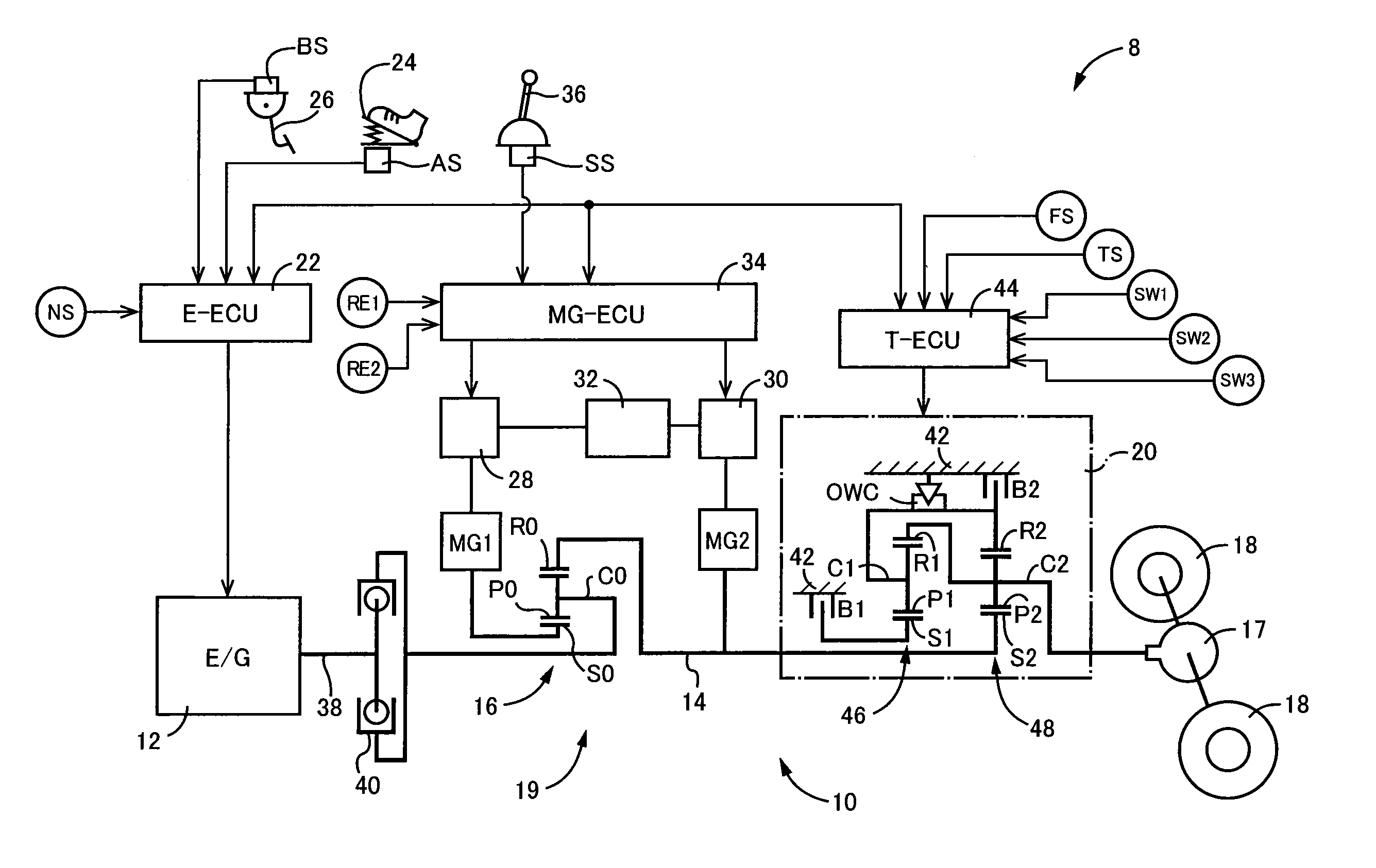
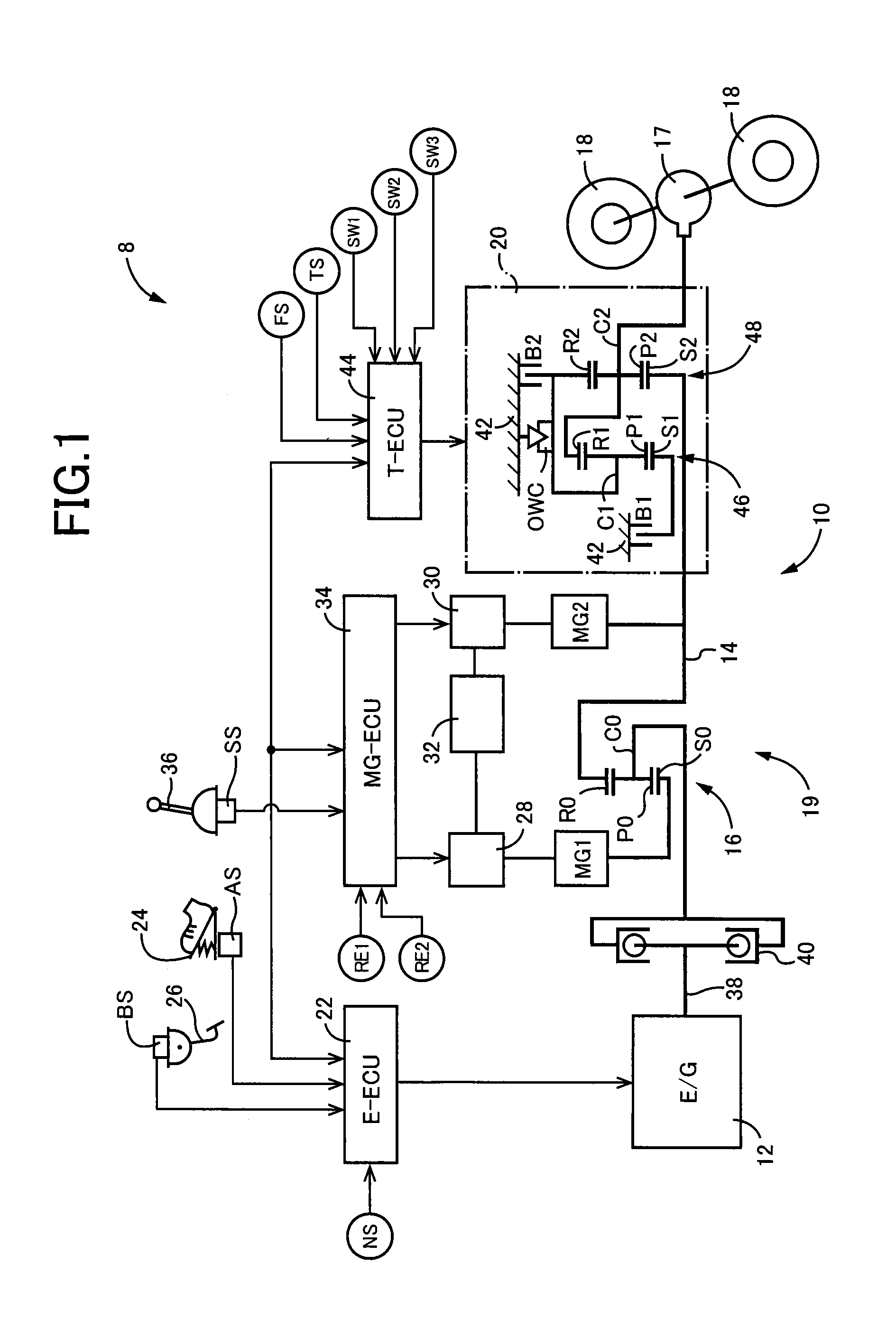
[0028]FIG. 1 is the view for explaining a hybrid vehicle 8 to which the present invention is suitably applicable. The hybrid vehicle 8 shown in FIG. 1 is suitably used as an FR (front-engine rear-drive) vehicle, for example, and is provided with a power transmitting system 10 having a power distributing device 16 configured to distribute a drive force generated by a main drive power source in the form of an engine 12, to a first electric motor in the form of a first motor / generator MG1 (hereinafter abbreviated as “MG1”) and to a power transmitting member in the form of an output shaft 14. The power transmitting system 10 further has a second electric motor in the form of a second motor / generator MG2 (hereinafter abbreviated as “MG2”) connected through a mechanically operated step-variable transmitting portion 20 to a power transmitting path between the power distributing device 16 and drive wheels 18. Torques generated by the above-indicated engine 12 and MG1 are transmitted to the ...


PUM


Abstract

A control apparatus for a hybrid vehicle provided with an electrically operated continuously-variable transmitting portion and a step-variable transmitting portion, which control apparatus permits an adequate control of a shifting action of the step-variable transmitting portion, while reducing deterioration of fuel economy of the hybrid vehicle.
The control apparatus is configured to implement concurrent controls of a movement of an operating point of an engine and a shifting action of the step-variable transmitting portion, such that an electric energy generation/consumption balance value in an overall transmission mechanism consisting of the electrically operated continuously-variable transmitting portion and the step-variable transmitting portion is controlled by controlling a change of a rotary motion of each of at least one of a sun gear corresponding to a g-axis, a carrier corresponding to an e-axis and a ring gear corresponding to an m-axis, so that a shifting shock of the step-variable transmitting portion can be reduced while controlling the electric energy generation/consumption balance to a desired value.

Description

TECHNICAL FIELD[0001]The present invention relates to a control device for a hybrid vehicle provided with an electrically operated continuously-variable transmitting portion and a step-variable transmitting portion, and more particularly to improvements of the control device for reducing deterioration of fuel economy during shifting actions of the transmitting portions.BACKGROUND ART[0002]There is known a hybrid vehicle provided with an electrically operated continuously-variable transmitting portion, and a step-variable transmitting portion constituting a part of a power transmitting path between the electrically operated continuously-variable transmitting portion and drive wheels. One example of such a hybrid vehicle is provided with: an electrically operated continuously-variable transmitting portion having a differential mechanism, a first electric motor and a second electric motor; and a step-variable transmitting portion constituting a part of a power transmitting path between...

Claims


Application Information

Patent Timeline
Patent Type & Authority Applications(United States)
IPC IPC(8): B60W20/00B60W10/11B60W10/06B60L50/16
CPCB60K6/445B60W30/1882B60W10/08B60W10/101B60W10/115B60W20/00B60W30/19Y02T10/6239Y02T10/6286B60W10/11B60W20/30B60W2600/00Y10S903/93B60K6/547B60W10/105B60W10/06Y02T10/62B60K6/543B60W2556/00
Inventor OTSUBO, HIDEAKIISHIKAWA, NAOKINOHARA, HIDEHARUTSUTSUMI, TAKAHIKO
Owner TOYOTA JIDOSHA KK
Why Eureka
Try Eureka