Treatment device and method of use

a treatment device and a technology of a treatment device, applied in the direction of medical devices, valve details, operating means/releasing devices, etc., can solve the problems of patient death, patient suffering from respiratory disease, and affecting lung function, so as to avoid vacuum build-up, reduce or avoid pressure build-up

Active Publication Date: 2013-08-29
B&D ELECTROMEDICAL +1
View PDF7 Cites 22 Cited by
  • Summary
  • Abstract
  • Description
  • Claims
  • Application Information

AI Technical Summary

Benefits of technology

[0023]It is another advantage of a rotary proportional solenoid valve that the operational positions, i.e. the extremes of its reciprocating movement, can be varied. Thus, it can be arranged that the valve move further towards the inlet side of the pump than the outlet side of the pump, or vice versa. Also, it can be arranged that the valve dwells for a longer period of time at its operational position at the inlet side of the pump than at its operational position at the outlet side of the pump. In this way, the value of the negative pressure in the breathing tube will exceed the value of the positive pressure, and the average pressure over a cycle will be lower than atmospheric pressure. The average pressure could alternatively be greater than atmospheric if desired, and the average could change from cycle to cycle. For example, a cough programme could com

Problems solved by technology

If the bronchial secretions are allowed to remain in the lungs or bronchial passageways they can impair the lung function and/or harbour germs, and can ultimately cause the death of the patient.
A patient suffering from respiratory disease, however, will often not have sufficient cough function, i.e. even if the patient retains the stimulus to cough he or she will not be able to generate sufficient force to cough effectively so as to expel or release any built-up bronchial secretions.
Conventional ventilators which are adapted

Method used


Image

  • Treatment device and method of use
  • Treatment device and method of use
  • Treatment device and method of use

Examples


Embodiment Construction

[0028]The invention will now be described in more detail, by way of example, with reference to the accompanying drawings, in which:

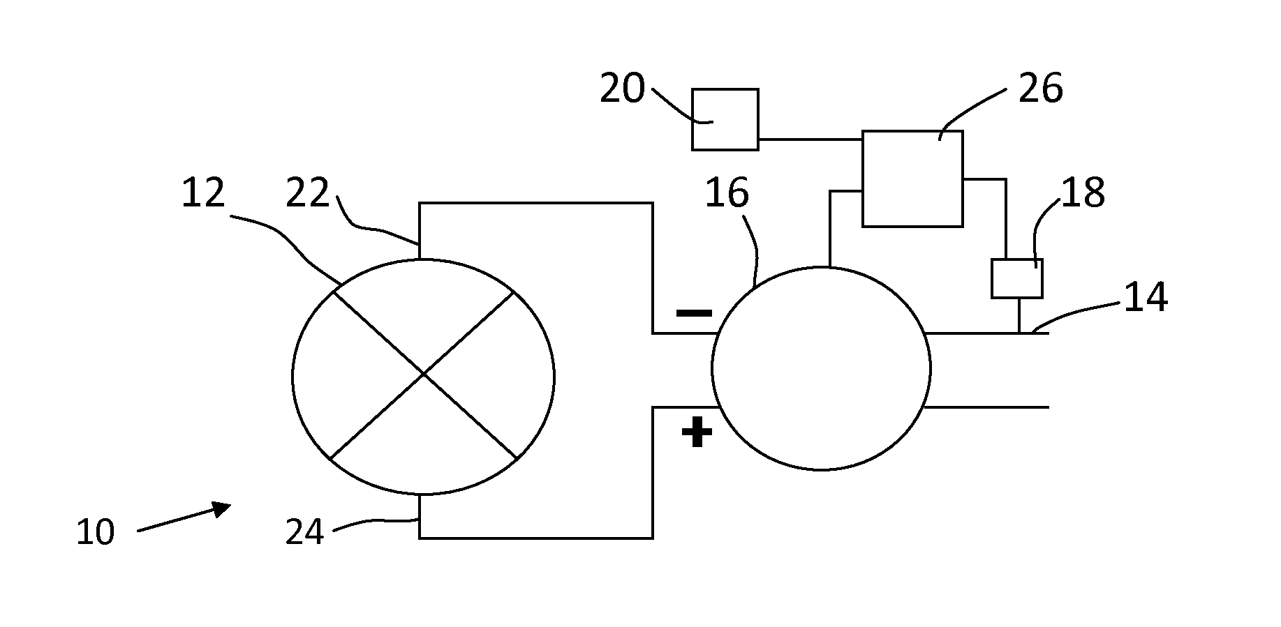
[0029]FIG. 1 shows a schematic representation of the treatment device of the present invention;

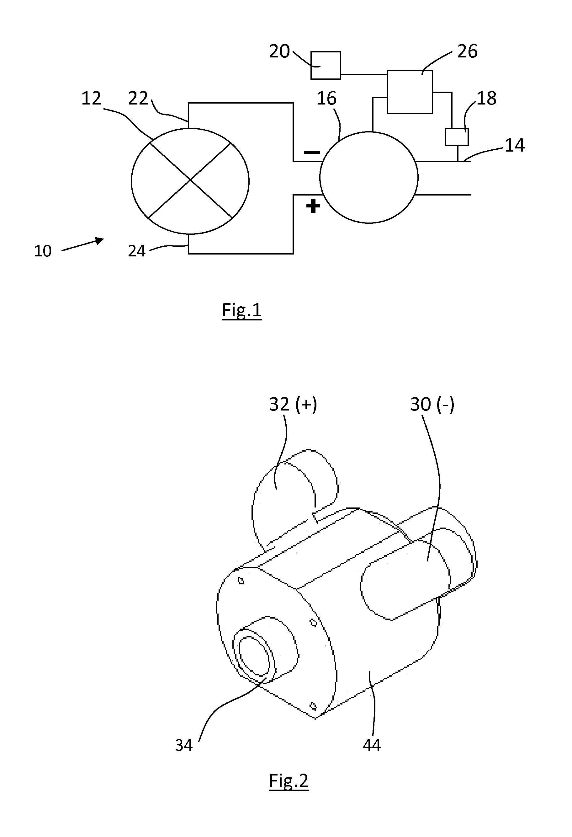
[0030]FIG. 2 shows a perspective view of the valve of the device;

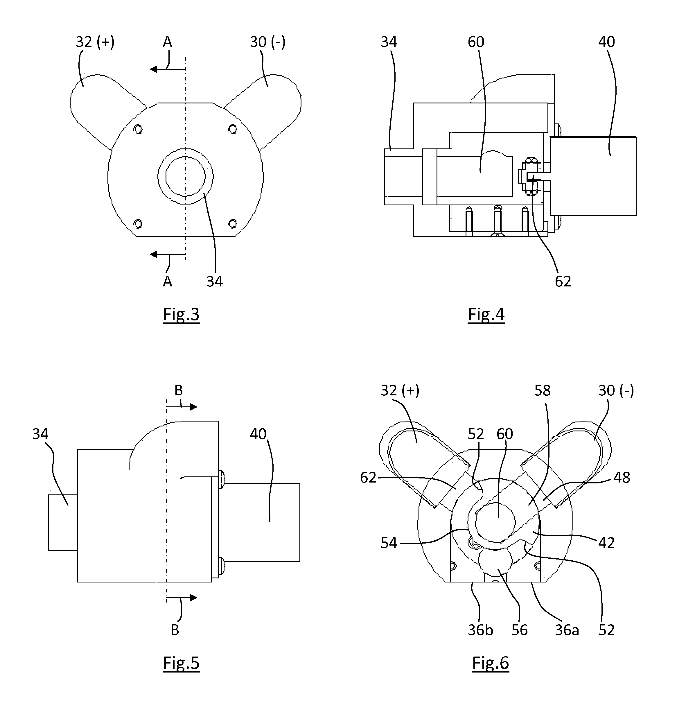
[0031]FIG. 3 shows an end view of the valve;

[0032]FIG. 4 shows a section along the line A-A of FIG. 3;

[0033]FIG. 5 shows a side view of the valve;

[0034]FIG. 6 shows a section along the line B-B of FIG. 5;

[0035]FIG. 7 shows an exploded view of the valve;

[0036]FIG. 8 shows an underside view of the valve; and

[0037]FIG. 9 shows a detailed view of the valve member.

DETAILED DESCRIPTION

[0038]The treatment device 10 comprises a pump 12, a breathing tube 14, a valve 16, a pressure sensor 18 and an indicator 20. The pump has an inlet side 22 and an outlet side 24. The pump preferably includes an impeller (not shown), although other suitable means of generating the required airflow and pressures can be provi...


PUM


Abstract

This invention relates to a treatment device (10) and method of use, and in particular to a treatment device adapted to assist the clearance of bronchial secretions in persons whose cough function is impaired. The invention provides a treatment device having a pump (12) with a negative pressure inlet side (22) and a positive pressure outlet side (24). The device has a breathing tube (14) for connection to a patient, and a pressure sensor (18) adapted to determine the pressure within the breathing tube. A valve (16) selectively connects the breathing tube to the inlet side or the outlet side of the pump whereby to provide cycles of positive and negative pressure within the breathing tube. A controller (26) is provided to control the valve. An indicator (20) alerts the patient to an operational status of the device so that the patient can breathe in time with the device and in particular can seek to cough at the same time as the pressure within the breathing tube is rapidly reduced.

Description

FIELD OF THE INVENTION[0001]This invention relates to a treatment device and method of use, and in particular to a treatment device adapted to assist the clearance of bronchial secretions in persons whose cough function is impaired.BACKGROUND TO THE INVENTION[0002]Many patients, in particular those suffering from respiratory diseases, are unable to cough for themselves, and require the assistance of a machine which can provide a series of positive and negative pressure cycles, alternately forcing air into the patient's lungs and allowing air to flow out of the patient's lungs. (The term “positive pressure” is used herein to mean a pressure above the ambient atmospheric pressure, and the term “negative pressure” is used to mean a pressure below the ambient atmospheric pressure).[0003]The lungs and bronchial passageways of a person suffering from respiratory disease will usually continue to secrete fluids to keep the bronchial tract moist, as in a healthy person, although in some pati...

Claims


Application Information

Patent Timeline
IPC IPC(8): A61M16/20A61M16/08A61M16/00
CPCA61M16/00A61M2016/0021A61M2205/3337A61M2205/581A61M2205/583A61M16/205A61M16/0057A61M16/0875A61M16/0009A61M16/0069A61M16/204A61M16/20A61M16/022
Inventor DAVIS, NOEL MARTINBACHELOR, PETER JOHN
Owner B&D ELECTROMEDICAL
Why Eureka
Try Eureka